Methods and apparatuses for positioning within an internal channel

a technology of internal channel and positioning method, which is applied in the field of scan imaging, treatment and/or measurement of the interior of the internal channel, can solve the problems of light energy loss, loss of desired image resolution, and inability of current optical coherence tomography (oct) systems to image more than about 1-2 mm into blood or tissue, so as to reduce blockage

Inactive Publication Date: 2015-03-17
ABBOTT CARDIOVASCULAR
View PDF49 Cites 4 Cited by
  • Summary
  • Abstract
  • Description
  • Claims
  • Application Information

AI Technical Summary

Benefits of technology

[0020]In one embodiment, a catheter assembly has a distal portion that can be changed from a configuration with a small overall radius suitable for traversing the internal channel to another configuration that is suitable for scanning at least a section of the interior wall of an internal channel, such as an artery. In one example, to eliminate or reduce the blockage effect of the blood in Optical Coherence Tomography (OCT) scanning, the distal portion spirals into gentle contact with (or closer to) a section of the artery wall for imaging along a spiral path for the detection of a significant vulnerable plaque. The spiral radius may be changed through the use of a guidewire, a tendon, a spiral balloon, a tube, or others. In another example, a spiral balloon is used to clear the blood out of the way between a spiral section of the vessel wall and the imaging sheath without blocking the blood flow in the artery. In one example, a catheter assembly similar that for scan imaging is used for the effective application of light to vessel wall tissues for purposes of photodynamic therapy. To reduce the blockage effect, the core for the application of light is housed in the sheath that can spiral into gentle contact with (or closer to) a section of the blood vessel wall, or in the sheath that has a balloon inflatable to clear the blood between the sheath and the section of the blood vessel wall, to ensure that the desired section of the vessel wall was irradiated with the light to an effective / sufficient / desired degree. In one example, a similar catheter assembly is used for the effective light collecting without projecting light, such as for optical temperature determination. To reduce the blockage effect, the core for the light receiving device (e.g., such as a fiber optic assembly, a core or an imaging core for connection to optical temperature determination devices) is housed in the sheath that can spiral into gentle contact with (or closer to) a section of the blood vessel wall, or in the sheath that has an outside balloon inflatable to clear the blood between the sheath and the section of the blood vessel wall.
[0022]In one embodiment, the distal portion of the elongated assembly does not severely block a flow of the blood or other tissue in the vessel in the second configuration (e.g., in second configuration the distal portion does not block a flow of the blood in the vessel significantly more than in the first configuration).
[0030]In one embodiment, the guide structure is operable at the proximal portion of the elongated assembly to: reduce a spiral length of the sheath to increase a spiral diameter of the sheath; and increase the spiral length of the sheath to reduce the spiral diameter of the sheath. In one embodiment, the guide structure is operable at the proximal portion of the elongated assembly to: reduce a number of spiral turns of the sheath to increase a spiral diameter of the sheath; and increase a number of spiral turns of the sheath to reduce the spiral diameter of the sheath.
[0036]In one aspect of an embodiment, an assembly to be inserted into a vessel, includes: a sheath to house a core movable along the sheath to scan at least a portion of a vessel; and a balloon enclosing at least a portion of the sheath along the sheath. The core is capable of at least one of: projecting an optical beam onto a portion of the vessel and receiving a light from a portion of the vessel. When inflated the balloon clears at least a portion of a light path between the sheath and the vessel to reduce blockage. In one example, the balloon is of a spiral shape, spiraling around the sheath. The sheath has a stiffness and is formed to remain substantially straight when the balloon of the spiral shape is inflated. In one example, the core projects an optical beam to receive a reflected light for optical coherence tomography; and the balloon is substantially transparent to the optical beam. In one example, the balloon is movable relative to the sheath (e.g., slidable along the sheath or rotatable about the sheath).

Problems solved by technology

Current Optical Coherence Tomography (OCT) systems are not able to image more than about 1-2 mm into blood or tissue.
Use of lights of longer wavelengths may avoid the red blood cell interaction but result in a loss of a desired image resolution.
In addition, there are light energy losses due to absorption and path length changes due to scattering (reflection) by the red cells.
Various techniques and devices have been used to flush blood from the imaging area with limited success.
However there are several problems and limitations with flushing, especially in an artery.
First, when enough saline solution or other isotonic biocompatible water-based solution is introduced to replace or dilute the blood, the amount of oxygen in the solution is very small in comparison to the amount of oxygen contained in the blood.
Thus, the time window for imaging is limited by the ischemic consequences of the solution on the heart muscle (e.g., reduction in blood flow).
The longer the duration of the flush, the more severe the consequences are to the heart muscle.
Second, blood flow in coronary arteries is laminar and generally tends to flow in streamlines, not mixing very rapidly with adjacent streamlines.
Third, most water-based flushing solutions have a viscosity that is significantly less than that of blood.
Fourth, in most injection configurations, the required high flush flow rate enters the artery via a relatively small flow cross section, resulting in a very high injection velocity.
This may create high velocity jets of flush, which can damage vessel walls.
Additionally, the pressures and volumes required are not easily accomplished by manual injection.
Moreover, contrast agents are quite expensive relative to normal flushing solutions.
Changing the index of refraction on a systemic level is very difficult and can be toxic.
However, changing the index of refraction outside of the patient's body requires extra equipment and a time-consuming index matching procedure and introduces issues involving increased blood exposure (e.g., to the environment).
Moreover, the streamline and injection problems discussed above would still be a challenge, and hemolysis (e.g., the destruction or dissolution of red blood cells, with subsequent release of hemoglobin) could be an added issue to consider.
A similar blockage of the light used in photodynamic therapies may also be a problem and may require similar saline flushing or blood dilution.

Method used


Image

  • Methods and apparatuses for positioning within an internal channel
  • Methods and apparatuses for positioning within an internal channel
  • Methods and apparatuses for positioning within an internal channel

Examples


Embodiment Construction

[0058]The following description and drawings are illustrative of the invention and are not to be construed as limiting the invention. Numerous specific details are described to provide a thorough understanding of the present invention. However, in certain instances, well known or conventional details are not described in order to avoid obscuring the description of the present invention. References to one or an embodiment in the present disclosure are not necessarily references to the same embodiment; and, such references mean at least one.

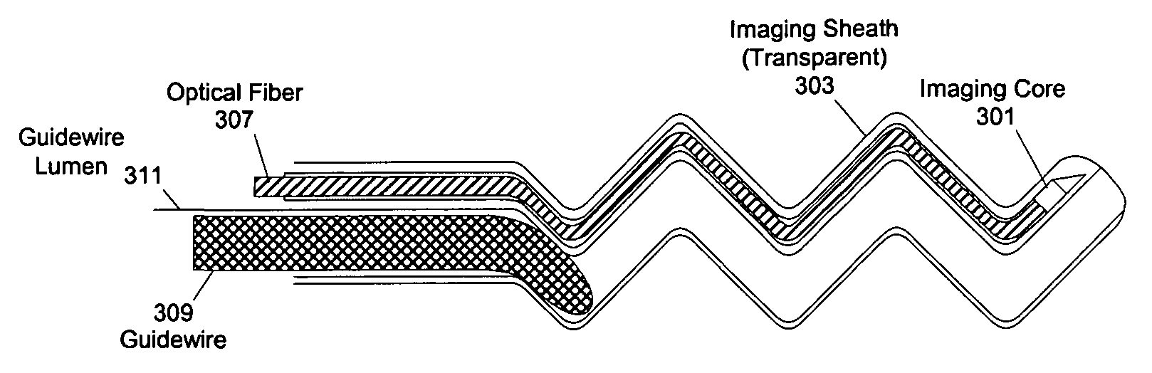
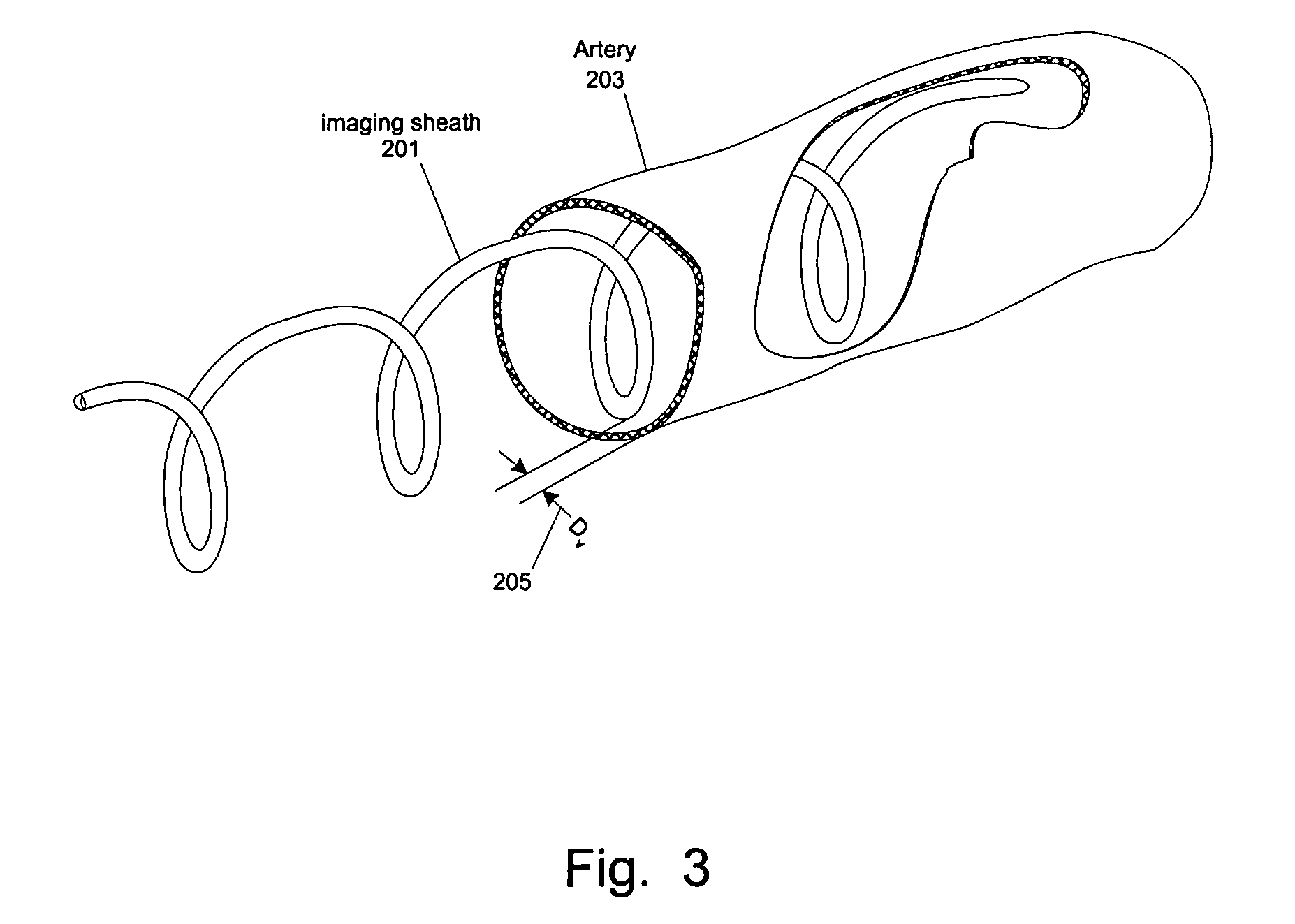
[0059]At least one embodiment of the present invention seeks to eliminate or reduce the effect of blood on the imaging of a blood vessel without the need for flushing. While flushing the blood vessel can reduce the effect of the blood on the image quality, flushing has a few drawbacks and problems. In at least one embodiment of the present invention, an imaging sheath spirals against the blood vessel for imaging so that the imaging sheath and a des...


PUM


Abstract

Methods and apparatuses for positioning medical devices onto (or close to) a desired portion of the interior wall of an internal channel, such as for scan imaging, for photodynamic therapy and / or for optical temperature measurement. In one embodiment, a catheter assembly has a distal portion that can be changed from a configuration suitable for traversing the internal channel to another configuration suitable for scan at least a spiral section of the interior wall of an internal channel, such as an artery. In one example, the distal portion spirals into gentle contact with (or close to) a spiral section of the artery wall for Optical Coherence Tomography (OCT) scanning. The spiral radius may be changed through the use of a guidewire, a tendon, a spiral balloon, a tube, or other ways.

Description

FIELD OF THE TECHNOLOGY[0001]At least some embodiments of the present invention relate to scan imaging, treatment and / or measurement of the interior of an internal channel, such as blood vessels.BACKGROUND[0002]Imaging technologies have been developed for the visualization of the interior of an internal channel, such as a vein or artery. For example, current Optical Coherence Tomography (OCT) systems can image into tissue to a depth of about 1.2-1.7 mm. Analogous to ultrasound imaging, the imaging core of an OCT system projects an optical beam (e.g., a short coherence length infrared light) on the tissue and receives the reflected light from the tissue to construct an image of the tissue. An OCT based imaging system can provide higher resolution imaging than current ultrasonic systems, but to a shorter depth into the tissue.[0003]FIG. 1 illustrates a prior art imaging assembly catheter. In FIG. 1, the imaging assembly includes a sheath (109) to house and guide the imaging core, whic...

Claims


Application Information

Patent Timeline
Patent Type & Authority Patents(United States)
IPC IPC(8): A61B6/00A61B1/00A61B1/005A61B1/313A61B5/00A61B5/01A61B5/02A61B8/12A61B17/22A61B19/00A61F2/958
CPCA61B5/6852A61B1/0051A61B1/00096A61B1/3137A61B5/0062A61B5/0066A61B5/0084A61B5/01A61B5/02007A61B5/6853A61B5/6885A61B1/00183A61B8/12A61B2019/5234A61B2017/22081A61B2090/3735A61B5/0036A61B5/02055A61B5/6851A61B5/6857A61N5/0601A61N5/062A61N2005/0602
Inventor WEBLER, WILLIAM E.
Owner ABBOTT CARDIOVASCULAR
Why Eureka
Try Eureka