Plug for use in a beverage container

a beverage container and plug technology, applied in the direction of liquid transferring devices, caps, liquid handling, etc., to achieve the effect of saving the cost and reliable discharg

Active Publication Date: 2015-03-24
THERMOS LLC
View PDF13 Cites 35 Cited by
  • Summary
  • Abstract
  • Description
  • Claims
  • Application Information

AI Technical Summary

Benefits of technology

[0010]The present invention has been made to solve the aforementioned problems. That is, it is an object of the present invention to provide a plug for use in a beverage container that can be easily disassembled into a plug main body and a valve body without allowing a valve body cover to come off the valve body unintentionally. It is also an object of the present invention to provide a plug for use in a beverage container that can ensure the pouring of a content fluid, can enhance its sanitary quality by improving its washing / cleaning processes such that the resilient member is reduced from the valve body and the valve body itself is also made disassemble, and can save its cost by reducing the number of components.
[0016]According to the invention of the second aspect, the upper end of the valve body protrudes from the valve body cover, so that no matter whether the valve body is opened or not, the valve body cover is prevented from being unintentionally disengaged from the valve body due to the opening and closing device not contacting the valve body cover.
[0017]According to the invention of the third aspect, the valve body and the valve shall are separate from each other, and the valve shaft is provided with the valve body which closes the inlet of the fluid passage above the valve body. Thus, the diameter of the valve shaft is formed smaller than that of the valve body. For these reasons, even when the inner pressure of the container main body is high due to hot water or the like, this inner pressure can be released by first pushing a valve body of the valve shaft downward. That is, there can be avoided such a situation that the valve body becomes unable to be pushed downward due to the inner pressure, and the content fluid can thus be reliably discharged.
[0018]According to the invention of the fourth aspect, the resilient member can be replaced by the engagement plate. That is, a metal coil spring that was conventionally provided in the fluid passage, for example, is no longer required, thereby making the plug sanitary, and saving the cost thereof by decreasing the number of components thereof at the same time.

Problems solved by technology

However, such disassemblable structure results in such a troublesome procedure that a user has to rotate the valve body cover while holding one hand against it at the same time as holding the other hand against the valve body.
However, if a metal spring is used as the resilient member 104, such structure undesirably allows the metal spring to be contacted by a content fluid, because the metal spring faces the fluid passage.

Method used


Image

  • Plug for use in a beverage container
  • Plug for use in a beverage container
  • Plug for use in a beverage container

Examples


first embodiment

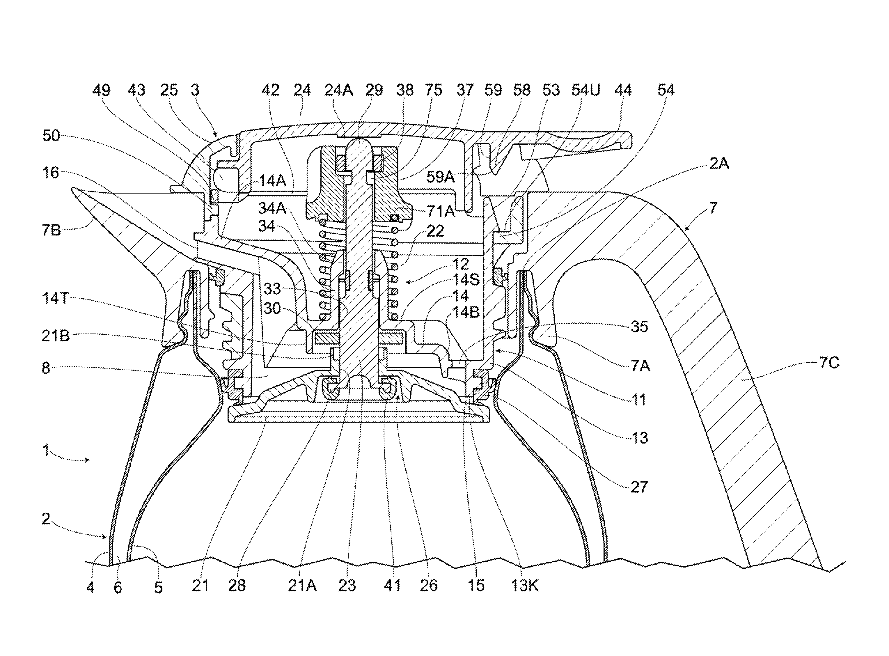
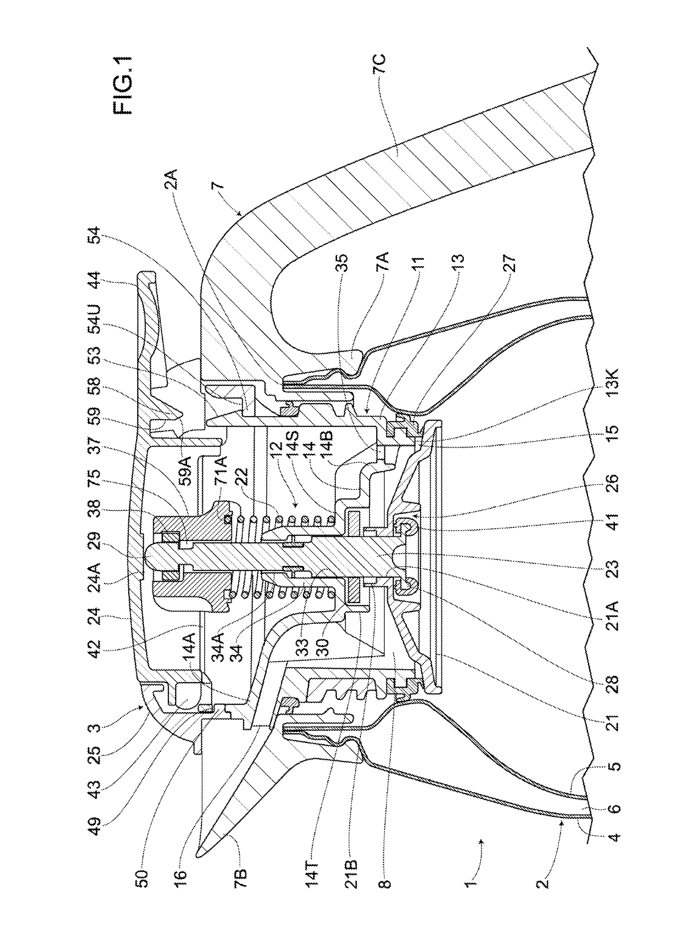
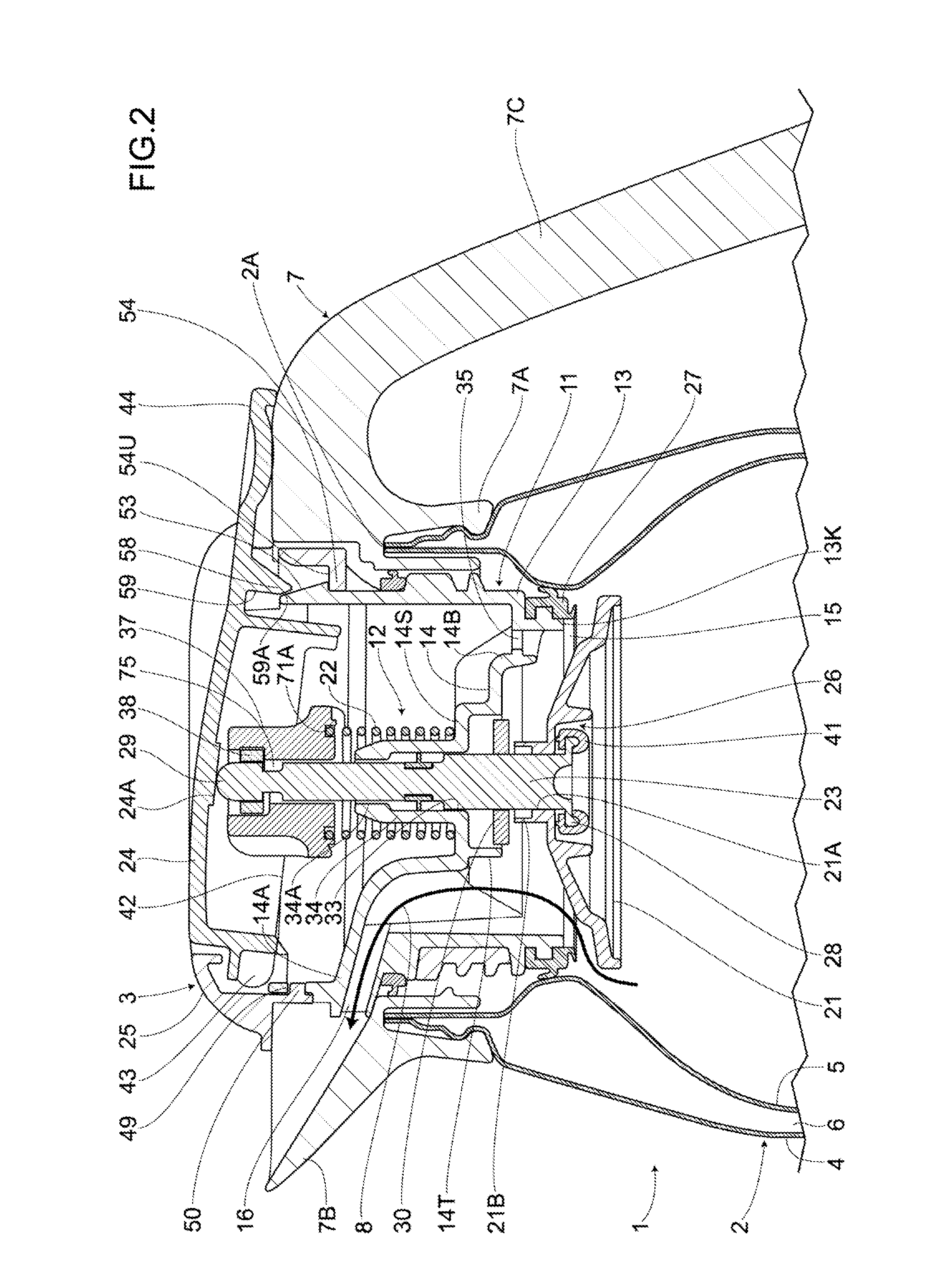
[0047]FIG. 1 through FIG. 23 show a first embodiment of the present invention. A beverage container 1 which is a thermos bottle, includes: a container main body 2; and a plug 3 that can be detachably attached to an upper opening section 2A of the container main body 2. The container main body 2 includes: an inner container 5; an outer container 4; and a heat-insulating layer (provided between such inner container 5 and outer container 4. Particularly, each of the inner container 5 and the outer container 4 is made of stainless steel and has an opened upper portion. More particularly, upper ends of the inner container 5 and the outer container 4 are integrally joined to each other with a shoulder member 7 being further integrally disposed on an upper portion formed b such inner container 5 and outer container 4. Here, the shoulder member 7 is made of a synthetic resin and is vertically disposed on an opened section formed by the inner container 5 and the outer container 4 that are jo...

second embodiment

[0114]FIG. 24 and FIG. 25 show the second embodiment of the present invention. Compared to the first embodiment, the same numbers are applied to the same parts in the second embodiment, and descriptions of the same parts thereof are skipped. The second embodiment is an example that the valve body 21 and the valve shaft 23 are integrally formed. According to this example, the shaft portion 29 of the valve shaft 23 is protrudedly provided on the center of the valve body 21, and the pressure reducing unit 26 and the engagement plate 30 are not provided. Also, according to this example, since the engagement plate 30 is not provided, it is not necessary that the shaft portion 29 is provided with the vertical grooves 31, 31 and the engagement grooves 31A, 31A.

[0115]According to the second embodiment, the plug also includes: a resilient member 22 that is provided on the valve body 21 and serves to bias the valve body 21 in a closing direction; a valve body cover 37 attached to the valve bo...


PUM


Abstract

The plug includes: a resilient member that is provided on the valve body and serves to bias the valve body in a closing direction; a valve body cover attached to the valve body in order to prevent the resilient member from coming of a rotation member rotatably provided on the valve body cover; at least two engagement claw portions that are provided on the rotation member and serve to allow the valve body cover to be engaged with an upper portion of the valve body; and claw guiding grooves and the recessed grooves serving as steps that are provided on an upper portion of the valve body, the number of the claw guiding grooves being equal to the number of or the integral multiple of the engagement claw portions, the recessed grooves allowing the rotation member to rotate.

Description

BACKGROUND OF THE INVENTION[0001]1. Field of the Invention[0002]The present invention relates to a plug for use in a beverage container such as a thermos bottle. Particularly, the present invention relates to a plug having a valve structure, and allowing a content fluid to be poured out when attached to a beverage container.[0003]2. Description of Related Art[0004]Conventionally, a plug for use in a beverage container comprises a plug main body having a fluid passage allowing a content fluid to be poured therethrough when tilting the beverage container and a valve structure capable of opening and sealing the fluid passage. The valve structure includes: a valve shall provided in the plug main body and capable of moving up and down; a valve body supported in a lower end of the valve shaft and capable of opening and sealing the fluid passage; a biasing means biasing the valve body in a sealing direction; and a control lever allowing the valve body to be opened when pushed down against ...

Claims


Application Information

Patent Timeline
Patent Type & Authority Patents(United States)
IPC IPC(8): A47G19/00A47G19/12B65D83/00B67D3/00B67D7/06F16K35/00A47J41/00B65D59/02
CPCB65D59/02A47J41/0027A47G19/12A47J41/02B65D47/2012
Inventor TACHI, KATSUAKI
Owner THERMOS LLC
Why Eureka
Try Eureka