Recording apparatus and recording method
a recording apparatus and recording method technology, applied in the direction of printing, thin material processing, other printing apparatus, etc., to achieve the effect of suppressing the generation of bubbles
- Summary
- Abstract
- Description
- Claims
- Application Information
AI Technical Summary
Benefits of technology
Problems solved by technology
Method used
Image

Examples
first embodiment
[0034]FIG. 1 and FIG. 2
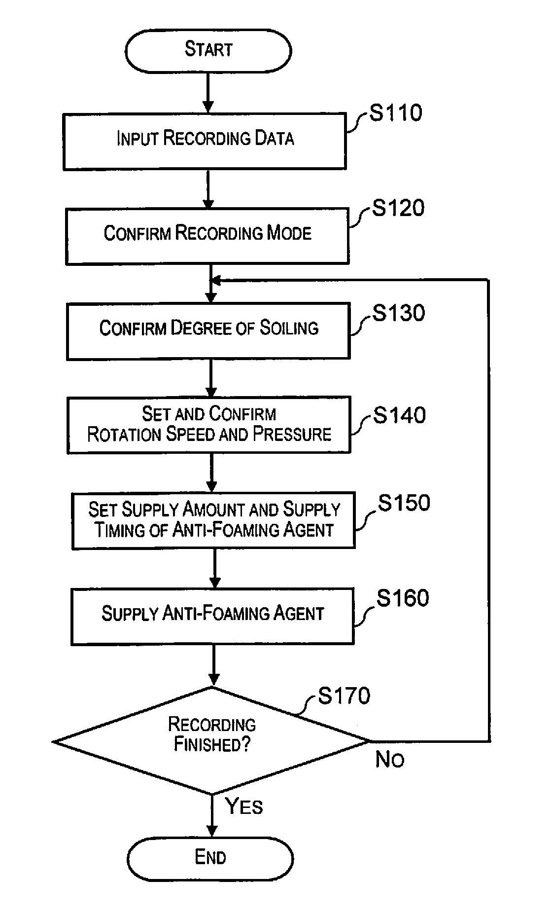
[0035]Below, a recording apparatus according to an embodiment of the present invention will be described in detail with reference to the accompanying drawings.
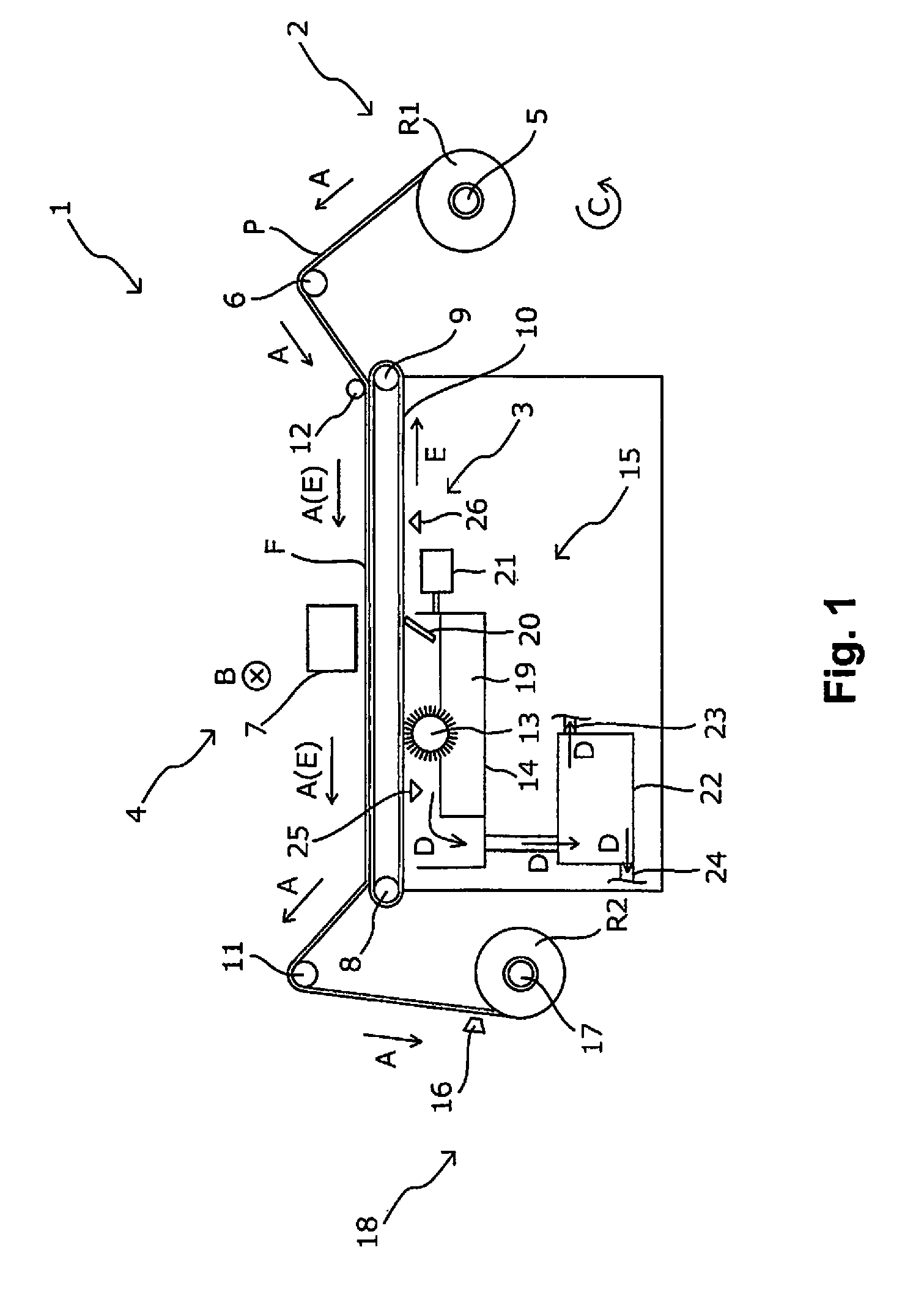
[0036]FIG. 1 is a schematic side surface diagram of a recording apparatus 1 according to a first embodiment of the present invention.
[0037]The recording apparatus 1 of the present embodiment is provided with a feeding section 2 which is able to feed out a roll R1 of a recording medium P in order to perform recording. In addition, a transport mechanism 3 is provided which transports the recording medium P in a transport direction A using an adhesive belt 10 which supports the recording medium P on a support surface F where an adhesive is attached. In addition, a recording mechanism 4 is provided which records by a recording head 7 scanning back and forth in an intersecting direction B which intersects with the transport direction A of the recording medium P. In addition, a cleaning mechanism 15 of the adh...
second embodiment
[0063]FIG. 3
[0064]Next, a recording apparatus according to a second embodiment of the present invention will be described.
[0065]FIG. 3 is a schematic side surface diagram of the recording apparatus 1 according to the second embodiment of the present invention. Here, the constituent members which are common to the embodiment described above are illustrated with the same reference numerals and detailed description of these constituent members will be omitted.
[0066]Only the anti-foaming agent supply position according to the anti-foaming agent supply section 21 in the recording apparatus 1 of the present embodiment is different to the recording apparatus 1 of the first embodiment.
[0067]In detail, the recording apparatus 1 of the present embodiment has a configuration where the anti-foaming agent is supplied to the rotating brush 13. According to this configuration, it is possible to effectively supply the anti-foaming agent at the contact section of the rotating brush 13 and the adhesi...
third embodiment
[0068]FIG. 4
[0069]Next, a recording apparatus according to a third embodiment of the present invention will be described.
[0070]FIG. 4 is a schematic side surface diagram of the recording apparatus 1 according to the third embodiment of the present invention. Here, the constituent members which are common to the embodiments described above are illustrated with the same reference numerals and detailed description of these constituent members will be omitted.
[0071]Only the anti-foaming agent supply position according to the anti-foaming agent supply section 21 in the recording apparatus 1 of the present embodiment is different to the recording apparatuses 1 of the first embodiment and the second embodiment.
[0072]In detail, the recording apparatus 1 of the present embodiment is configured to supply anti-foaming agent toward the wiper 20. According to this configuration, it is possible for the wiper 20 to eliminate bubbles when recovering bubbles which originate from ink which are genera...
PUM
| Property | Measurement | Unit |
|---|---|---|
| pressure | aaaaa | aaaaa |
| side surface diagram | aaaaa | aaaaa |
| electrical configuration | aaaaa | aaaaa |
Abstract
Description
Claims
Application Information
 - R&D
- Intellectual Property
- Life Sciences
- Materials
- Tech Scout
- Unparalleled Data Quality
- Higher Quality Content
- 60% Fewer Hallucinations
Browse by: Latest US Patents, China's latest patents, Technical Efficacy Thesaurus, Application Domain, Technology Topic, Popular Technical Reports.
© 2025 PatSnap. All rights reserved.Legal|Privacy policy|Modern Slavery Act Transparency Statement|Sitemap|About US| Contact US: help@patsnap.com