Liquid cooled video projector

a liquid-cooled, projector technology, applied in the direction of magnetic variable regulation, measurement using nmr, instruments, etc., can solve the problems of exasperation, inadequate cooling, eerie and unnatural experience for patients, etc., to maintain the temperature of the projector at a reduced level, the effect of removing gas cavities

Active Publication Date: 2015-03-24
AVOTEC
View PDF10 Cites 4 Cited by
  • Summary
  • Abstract
  • Description
  • Claims
  • Application Information

AI Technical Summary

Benefits of technology

[0011]The present invention satisfies this need by teaching a water cooled projector for use adjacent an MRI bore that permits proper cooling of the LCOS, LDP, LED, or the like based projector engine. The liquid cooling apparatus of the instant invention provides a means for direct dissipation of heat from the projector light through a heat sink body that is coupled to a remotely mounted fluid circulation system.
[0013]A liquid reservoir can be coupled to the pump intake for use in maintaining liquid levels at an optimum level to address evaporative losses and remove gas cavities.

Problems solved by technology

A problem with the bore is the extremely small area for placement of the patient and this leads to anxiety.
The large and ominous appearance of the scanner together with harsh low monotone sounds which include both soft and loud thumping, produces an eerie and unnatural experience for the patient.
If the patient is above average in size, the problem is exasperated.
A problem with introducing conventional audio or video signals into an MRI apparatus is that the MR imager is based upon the use of radio frequencies which will disrupt the audio or video signals.
However, the magnetic field from the MRI causes problems with the operation of a video projector.
However, the high heat fluxes of modern projectors, coupled with a need for a physically compact MRI-compatible projector, made these designs inadequate, and resulted in inadequate cooling and premature failure of the video projector.
A common characteristic of these light sources is that they generate considerable amounts of heat.
If this heat is not dissipated, the light source, image generation device or the projector electronics will be adversely affected.

Method used


Image

  • Liquid cooled video projector
  • Liquid cooled video projector
  • Liquid cooled video projector

Examples


Embodiment Construction

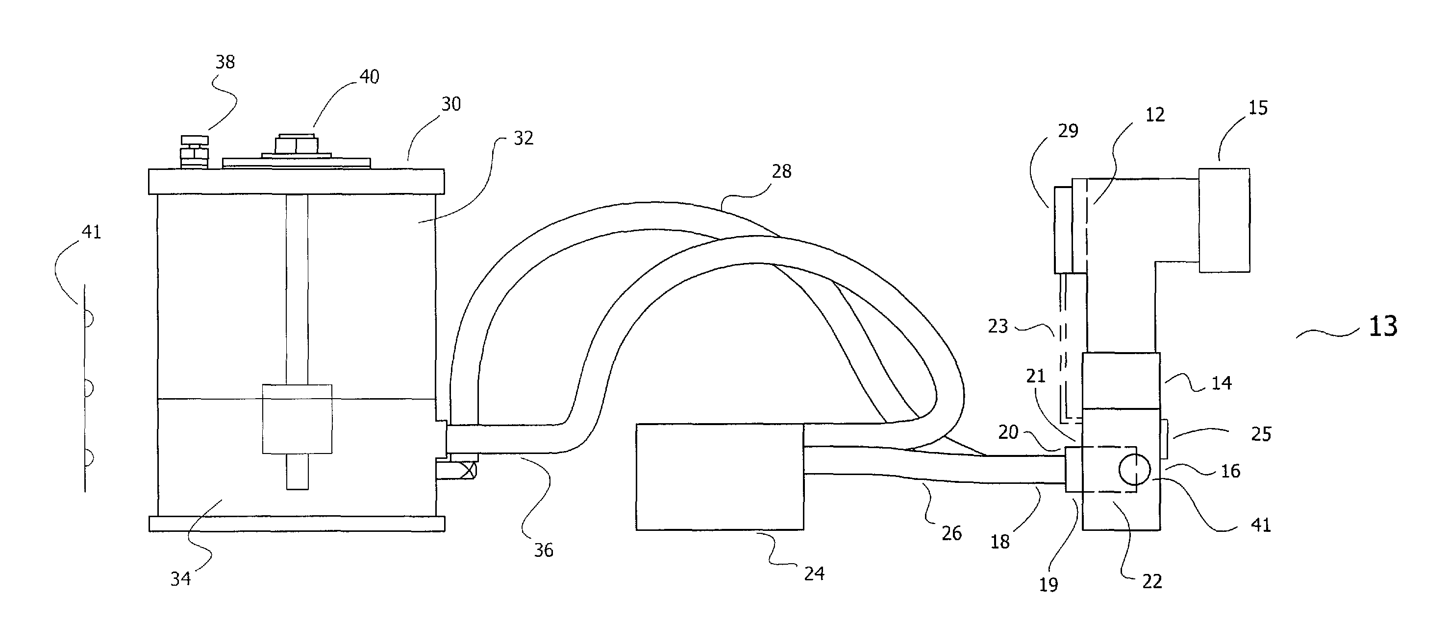
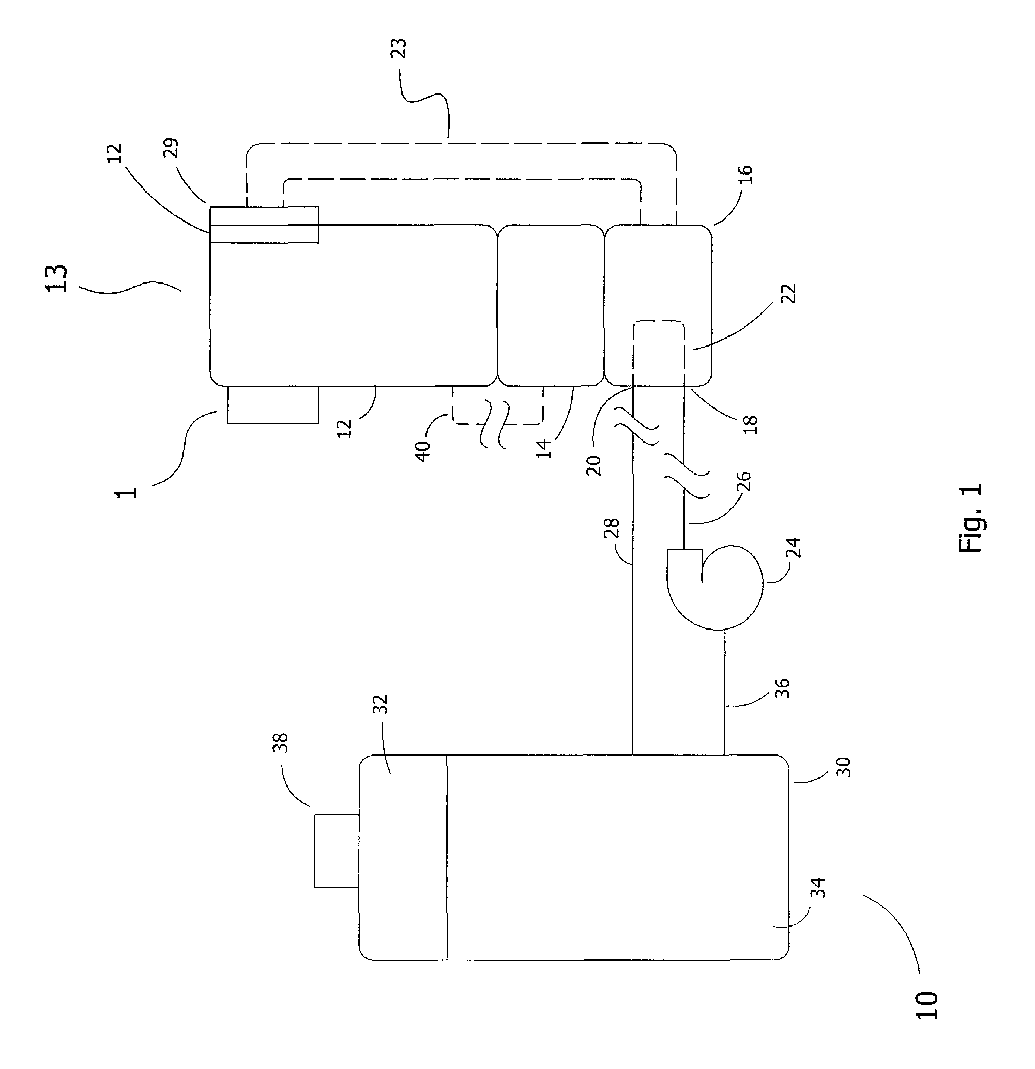
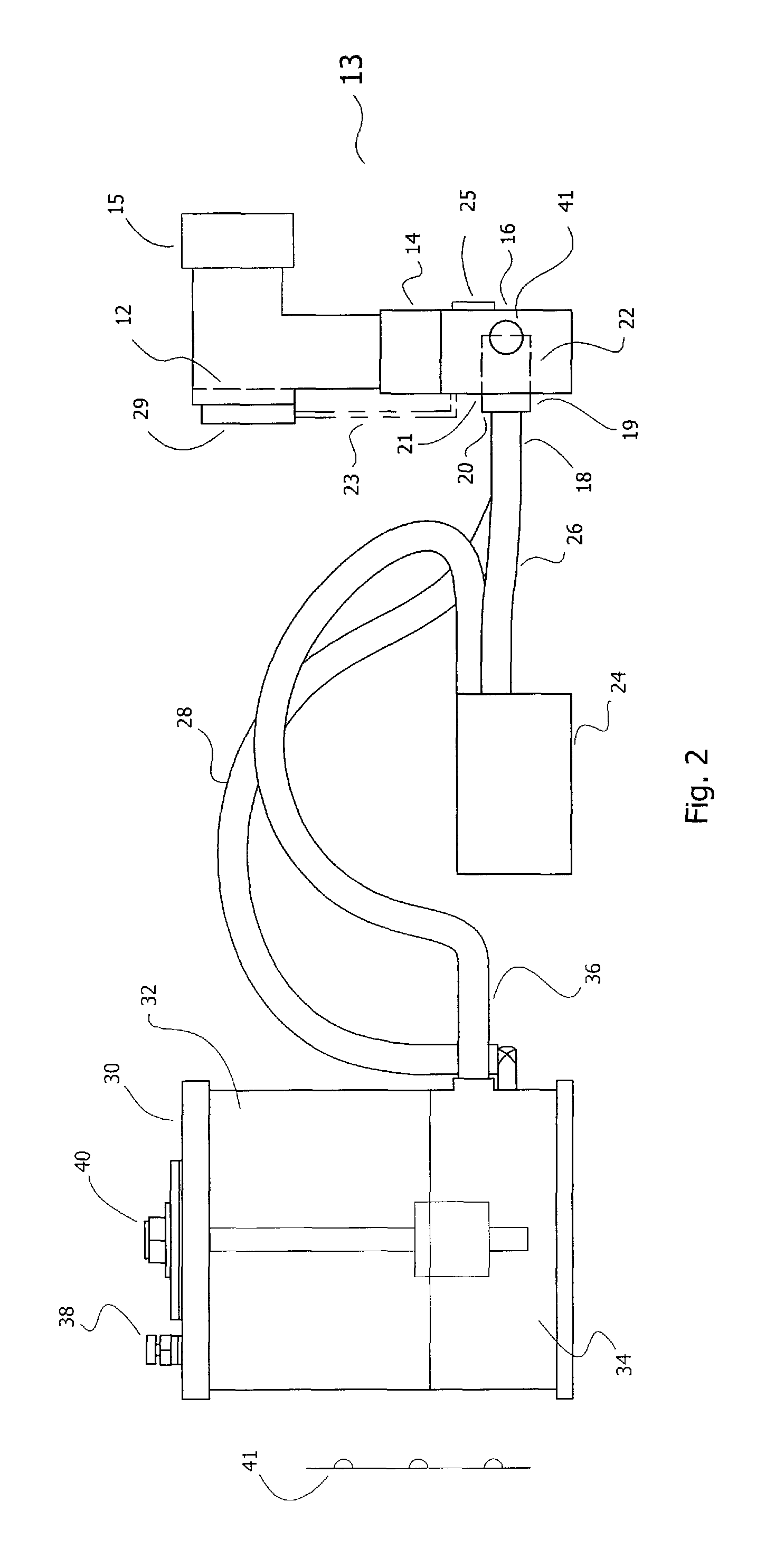
[0020]Referring now to the Figures in general, set forth is a liquid cooled system 10 for use with a video projector 1 installed adjacent to an MRI apparatus. The system 10 includes a heat sink block 16 constructed from a heat collecting material, on which the projector light 14 is mounted. In the preferred embodiment the heat collecting material is copper. It should be noted that most any material can be used that is capable of transferring heat between the projector light and the liquid circulation system, including aluminum or plastic.

[0021]The use of a water cooled projector allows the projector to be placed adjacent to an MRI bore and permits proper cooling of the LCOS, LDP, LED, or the like optical engine without the need for a cooling fan. Conventional cooling fans that employ magnetic drives are inoperative within the MRI field. The liquid cooling apparatus of the instant invention provides a means for direct dissipation of heat from the projector light through a remotely mo...


PUM


Abstract

Disclosed is a liquid cooling system for use with MRI positioned video projectors to dissipate heat from the projector light source through liquid cooling. The system includes a heat sink body for mounting to the projector light source, the heat sink body constructed of a material to transfer heat away from the projector light. A remotely mounted motor-driven pump provides fluid circulation, the pump is constructed and / or mounted so as to not to be effected by the MRI magnetic field. The pump is coupled to the heat sink block by use of flexible tubing that is constructed and arranged to provide heat transfer to the environment thereby maintaining the projector light source temperature at a reduced level. A liquid reservoir is fluidly coupled to the pump intake for use in maintaining liquid levels at an optimum position.

Description

PRIORITY CLAIM[0001]In accordance with 37 C.F.R. 1.76, a claim of priority is included in an Application Data Sheet filed concurrently herewith. Accordingly, under 35 U.S.C. §119(e), 120, 121, and / or 365(c) the present invention claims priority to U.S. Provisional Application No. 61 / 642,336, entitled “LIQUID COOLED VIDEO PROJECTOR”, filed May 3, 2012. The contents of which the above referenced application is incorporated herein by reference.FIELD OF THE INVENTION[0002]This invention relates to video projectors and in particular to an improved video projector apparatus for cooling a video projection system placed adjacent to a magnetic resonance imaging (MRI) system.BACKGROUND INFORMATION[0003]Magnetic Resonance Imaging (MRI) is a diagnostic device for use in imaging and exploring the internal body without surgery. An MRI has the ability to distinguish healthy and diseased tissue, fat and muscle, and between adjacent structures within the body which other modalities cannot demonstrat...

Claims


Application Information

Patent Timeline
Patent Type & Authority Patents(United States)
IPC IPC(8): G03B21/16G01R33/28G01R33/48
CPCG03B21/16G01R33/283G01R33/4806H04N9/3144
Inventor BULLWINKEL, PAUL E.
Owner AVOTEC
Why Eureka
Try Eureka