Minimum cavity relief valve

A pressure reducing valve and valve seat technology, applied in the field of pressure reducing valves, can solve problems such as blockage and agglomeration, valve inoperability, and valve uselessness

Inactive Publication Date: 2016-05-25
GRACO INC
View PDF7 Cites 0 Cited by
  • Summary
  • Abstract
  • Description
  • Claims
  • Application Information

AI Technical Summary

Problems solved by technology

The dead space may become clogged with agglomerated material rendering the valve inoperable
In some cases, the material may solidify or harden in the dead space, or otherwise gradually solidify, rendering the valve useless and frequently forcing its replacement

Method used


Image

  • Minimum cavity relief valve
  • Minimum cavity relief valve
  • Minimum cavity relief valve

Examples


Embodiment Construction

[0010] In this specification, references to "one embodiment" or "an embodiment" or "an example" or "example" in this specification are not intended to necessarily refer to the same embodiment or example; however, such embodiments are not mutually exclusive unless otherwise stated or otherwise apparent to one of ordinary skill in the art having the benefit of this disclosure. Accordingly, various combinations and / or integrations of the embodiments and examples described herein may be included, as well as other embodiments and examples defined within the scope of all claims based on this disclosure and all legal equivalents of such claims.

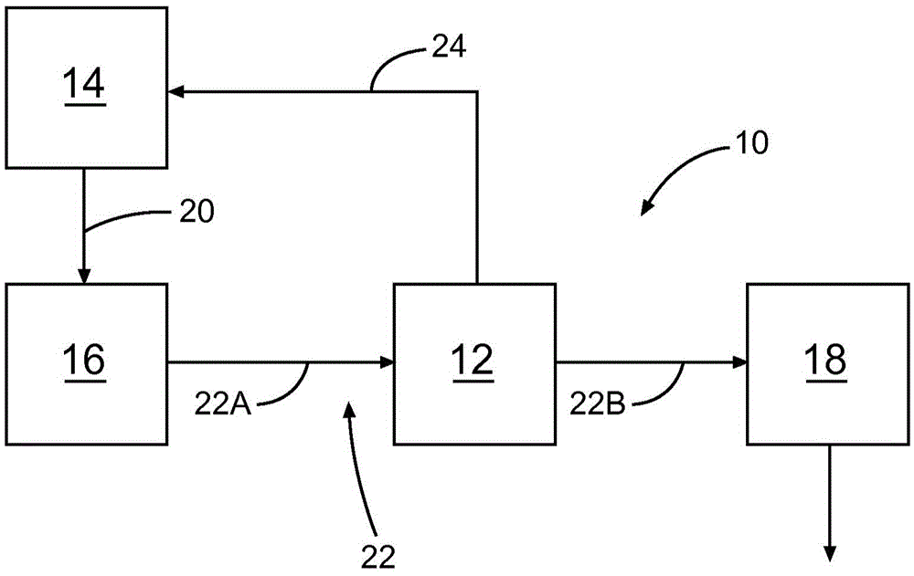
[0011] figure 1 is a schematic diagram of a pumping and injection system 10 in which a minimum cavity pressure reducing valve 12 according to the present invention may be used. System 10 includes container 14 , pump 16 and sparging mechanism 18 . Container 14 includes a hopper or other similar vessel into which material is held for pumping...


PUM


Abstract

The disclosure addresses a relief valve suitable for use in systems for delivering relatively viscous fluids. The described relief valve includes a housing and a valve mechanism moveable relative to an opening into the housing to allow or prevent flow from a flow path adjacent the relief valve into and through the housing. The relief valve is configured to minimize, and in many examples, essentially eliminate, a cavity between the housing opening and the adjacent flow path. Elimination of this cavity offers significant advantages as it minimizes or eliminates a location for pumped materials to accumulate and / or cure, which can lead to impairment or disabling of the relief valve operation.

Description

[0001] related application [0002] This application claims priority to US Provisional Patent Application No. 61 / 890,229, entitled "Zero-Cavity Pressure Relief Valve," filed October 12, 2013, which is hereby incorporated by reference in its entirety. technical field [0003] The present invention relates generally to pumping and injection systems, and more particularly, to pressure relief valves suitable for use in such pumping and injection systems. Background technique [0004] Peristaltic, piston and double diaphragm pumps are commonly used for pumping highly viscous materials. Pumps convey and inject materials under pressure from fluid slurries to heavy sand grouts such as cement slurries, sand-cement mixes, bentonite mixes (with or without sand), repair mortars, high-strength non-shrinkable grouts and Self-leveling products. Common characteristics of these materials are that they are generally fluid or semi-fluid, have a relatively high specific gravity and are genera...

Claims


Application Information

Patent Timeline
Patent Type & Authority Applications(China)
IPC IPC(8): F16K17/02F16K17/168
CPCB05B14/00F16K1/04F16K1/12F16K24/04F16L41/16B05B9/0403F16K27/02F16K31/60
Inventor 马丁·P·麦考密克赖安·F·巴特勒
Owner GRACO INC
Why Eureka
Try Eureka