
Dock connector with compliance mechanism

a technology of compliance mechanism and dock connector, which is applied in the direction of insulated conductors, coupling device connections, cables, etc., can solve the problems of placing additional stresses on the connector and the damage of the connector of such docking stations, so as to reduce the likelihood of breakage, reduce the likelihood of misuse, and flexible and durable

Active Publication Date: 2015-03-24
APPLE INC
View PDF65 Cites 43 Cited by
  • Summary
  • Abstract
  • Description
  • Claims
  • Application Information

AI Technical Summary

Benefits of technology

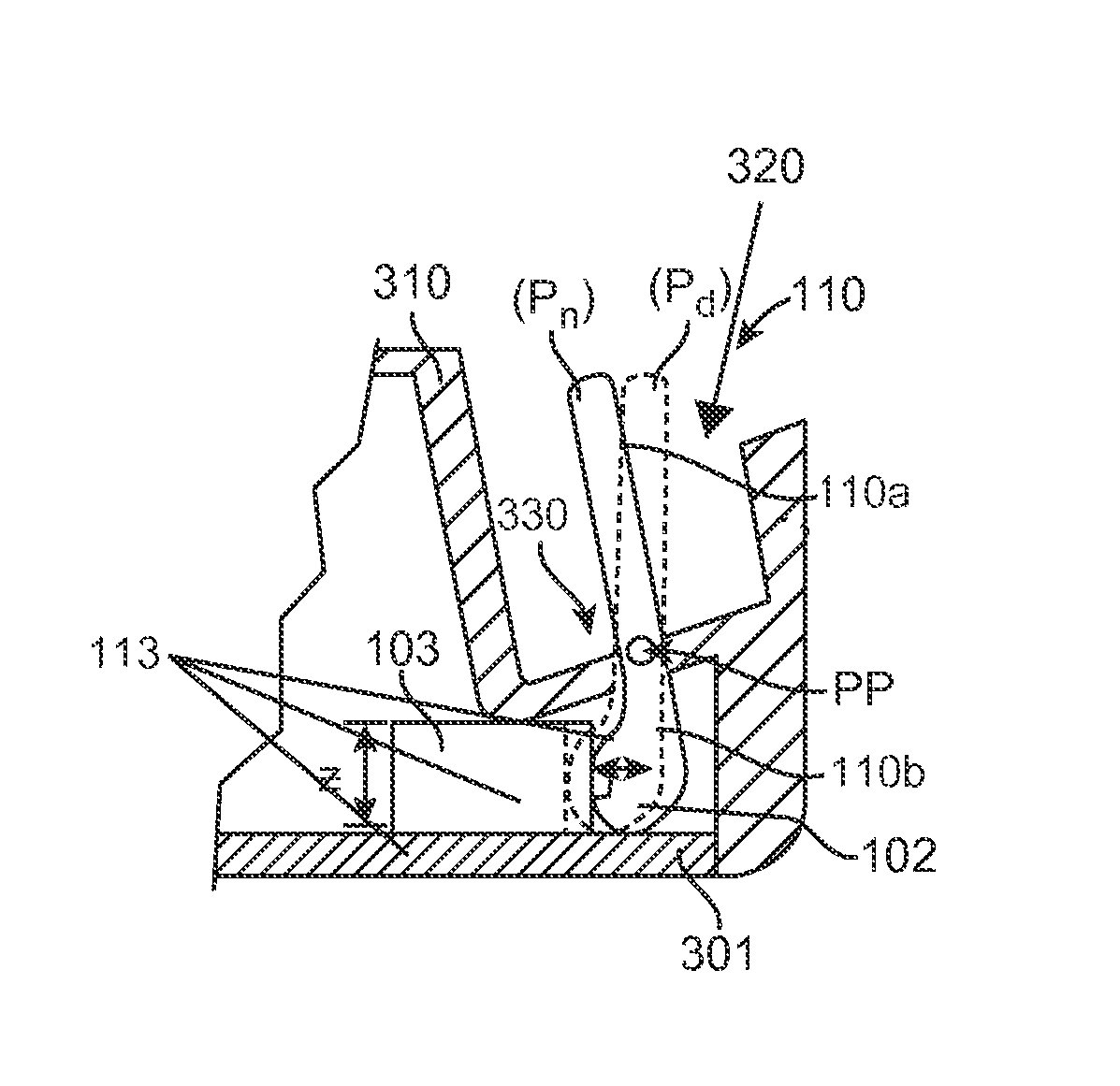
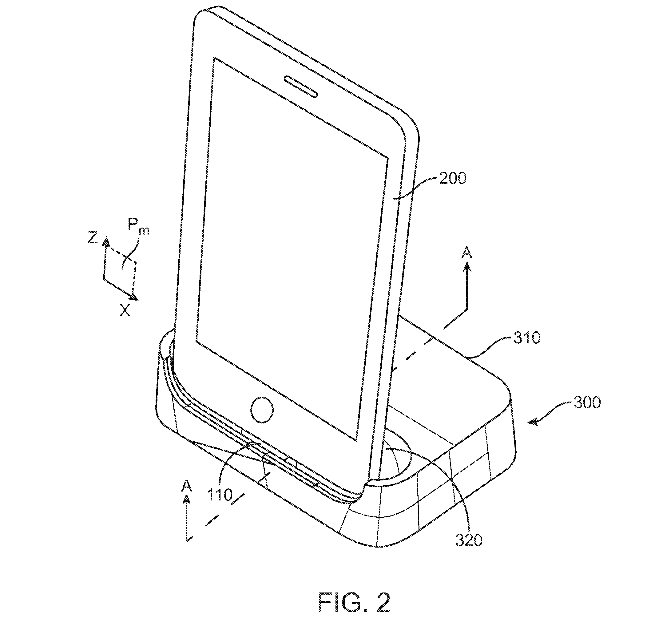
[0006]Embodiments of the present invention provide docking stations having a connector with a compliance mechanism that is more flexible and durable than conventional docks connectors. Some embodiments allow the connector to move relative the dock base when connected to a portable electronic device. This movement of the connector can absorb undesirable forces, thereby reducing a likelihood of the connector breaking from misuse. Examples of compliant movement include sliding, translation, flexures, rotation, sliding, rolling, pivoting and / or some combination thereof. For example, in some embodiments, if a mounted portable electronic device is manually pushed forward, the connector can rotate or pivot within the dock, thereby reducing the likelihood of breakage from such a push.
[0008]In another aspect, the compliance mechanism is configured with a resilient bias toward a particular position, such as an upright mounted position, in which an electronic device is supported by the compliance mechanism (and / or at least partly supported by a rear reference surface of the docking station), thereby inhibiting undue strain on the rotatable connector in the non-deflected position. The bias of the compliance mechanism can be controlled by the shape and material properties of the compliance mechanism, as well as its design and overall configuration. For example, in some embodiments, the compliance mechanism is configured to support the connector in an upright position that is tilted back slightly when the compliance mechanism is unstressed and unflexed so as to facilitate mounting of the device or viewing and operation of the portable device by a user when mounted in the dock. The connector may be disposed partly below and partly above an outer shell of a base of the docking station and pivot at a location on the connecter near an opening in the outer shell of the dock base through which the connector protrudes, thereby reducing movement of the connector near the opening. This aspect allows the opening in the shell or housing to be minimized and reduces the likelihood of interference between the connector and the dock shell or housing as the connector pivots.

Problems solved by technology

However, during such interfacing or charging, the user may still want to view the display and / or controls of the device.
However, the connectors can be weak points, especially when devices become large and heavy, placing additional stresses on the connector, particularly in connectors of relatively small size.
Accordingly, the connectors of such docking stations can be damaged by misuse, e.g. being pulled in improper direction.

Method used


Image

  • Dock connector with compliance mechanism
  • Dock connector with compliance mechanism
  • Dock connector with compliance mechanism

Examples


Embodiment Construction

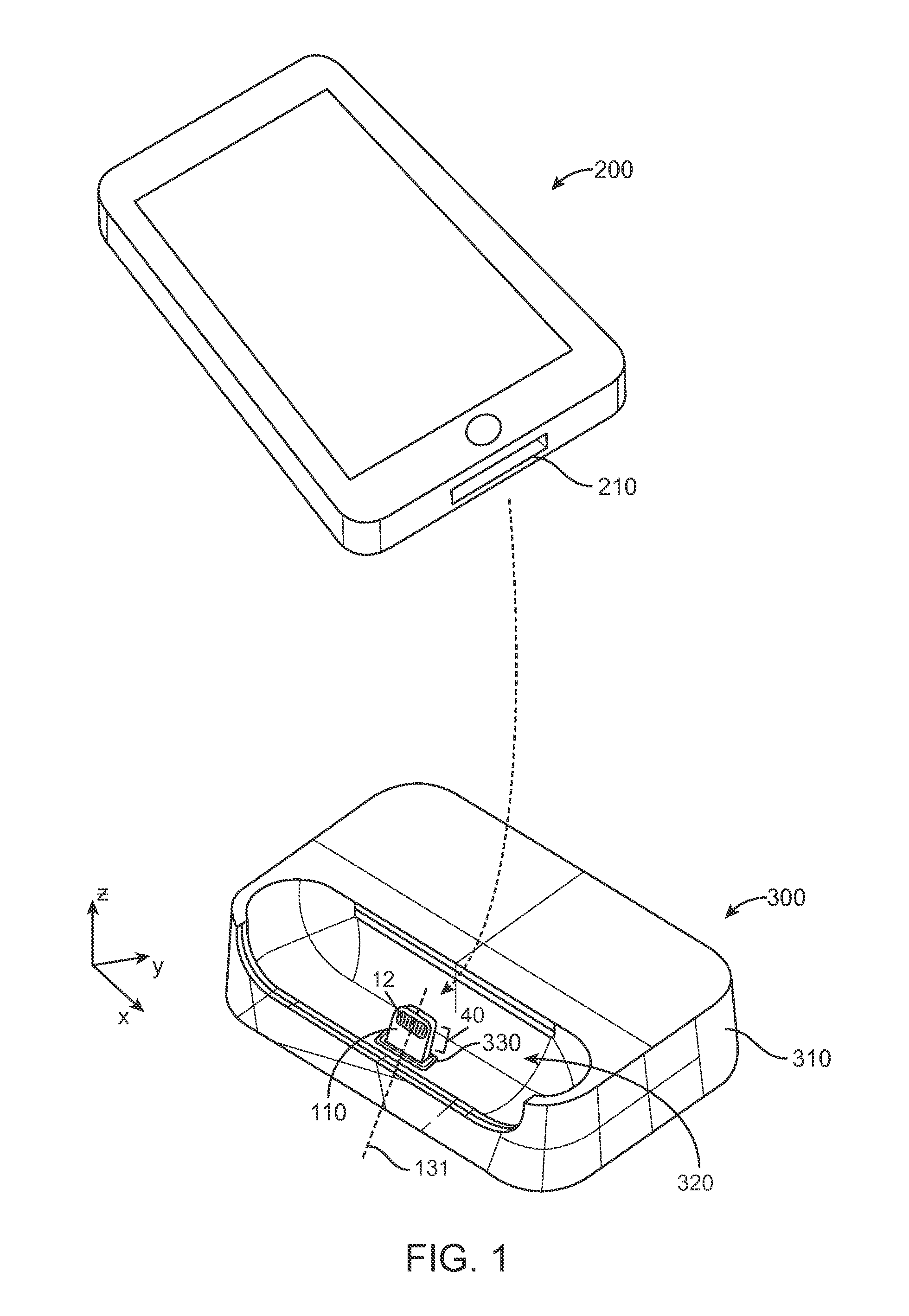
[0019]Embodiments of the present invention provide a docking station or dock having a connector with a compliance mechanism that allows for improved durability, flexibility and controlled compliant movement of the connector. These objectives can be accomplished, in part, by allowing the connector to move so that the connected portable electronic device does not subject the connector to a significant amount of force. For example, with limited reference surfaces (surfaces that can touch the electronic device when it is connected with the connector mounted in the dock), a joint of a fixed connector may weaken or break if the portable electronic device is forced off its attachment / detachment axis. Such a force may occur inadvertently when a user reaches for the device. In a dock in accordance with the present invention, the force of the push and / or the force of the weight of the device, which may weaken or compromise the joint in a conventional dock, instead simply moves the connector.

[...


PUM


Abstract

Docking stations having a connector with a compliance mechanism to provide improved durability and flexibility are provided herein. The compliance mechanism may be attached to a connecter in a base of a docking station that extends through an opening in a housing or shell attached to the base. The compliance mechanism may include any or all of a flexure, a torsion bar, damping members, a compressive foam member, and an engineered base plate. The compliance mechanism may be configured to provide sufficient rigidity to the connector to support a portable device when mounted on the connector within the dock in an upright position, sufficient flexibility to allow angular displacement of a mounted portable device, and sufficient elasticity to provide a resilient biasing force to return the connector and a mounted portable device from a displaced position to the upright position.

Description

CROSS-REFERENCES TO RELATED APPLICATIONS[0001]This application is a Non-Provisional Patent Application which claims priority from U.S. Provisional Application No. 61 / 699,838, filed on Sep. 11, 2012, the full disclosure of which is incorporated herein by referenceBACKGROUND[0002]The present invention relates to a docking station for an electronic device. More particularly, the present invention relates to a docking station having a compliant connector mount with improved durability and flexibility.[0003]Portable electronic devices (such as phones, media players, notebook / netbook computers, tablet computers) are becoming ubiquitous in today's society. Portable electronic devices commonly have display screens (e.g. a touch screen) on which users view and / or select data and functionality. For example, a user may select a video or other presentation to watch. In such circumstances, it is often more convenient for the user to have the device in an upright (viewable) position by placing th...

Claims


Application Information

Patent Timeline
Patent Type & Authority Patents(United States)
IPC IPC(8): H01R13/64H05K7/14
CPCH05K7/14H04M1/04H02J7/0044
Inventor WEBB, MICHAEL J.COLAHAN, IAN P.THOMPSON, PAUL J.
Owner APPLE INC
Learn More