Method of treating paravalvular leakage after prosthetic valve implantation

a technology of paravalvular leakage and prosthetic valve, which is applied in the field of devices and methods for treating paravalvular leakage after implantation of stented prosthetic valve, can solve the problems of valve not opening properly, insufficiency or regurgitation, stenosis and insufficiency, etc., and achieve the effect of increasing the tension of the captured chordae tendina

Active Publication Date: 2015-03-24
MEDTRONIC ARDIAN LUXEMBOURG SARL
View PDF17 Cites 16 Cited by
  • Summary
  • Abstract
  • Description
  • Claims
  • Application Information

AI Technical Summary

Benefits of technology

[0007]Embodiments hereof relate to a method for treating paravalvular leakage at a location of a stented prosthetic valve includes the steps of delivering a clip to a location adjacent chordae tendinae of a native valve, and deploying the clip such that the clip captures at least some of the chordae tendinae of the native valve, thereby increasing tension in the captured chordae tendinae. The clip is delivered to the location in a collapsed stated and is released from a sheath convert to an undeflected or relaxed state. After the clip is released from the sheath, the clip is rotated to capture the chordae tendinae. The clip is then released from the delivery system and the delivery system is retracted.

Problems solved by technology

Problems that may develop with valves include stenosis in which a valve does not open properly, and / or insufficiency or regurgitation in which a valve does not close properly.
Stenosis and insufficiency may occur concomitantly in the same valve.
The effects of valvular dysfunction vary, with mitral regurgitation or backflow typically having relatively severe physiological consequences to the patient.
Such surgical techniques are not desirable for certain patients.
However, after delivery and deployment of such a stent prosthetic mitral valve, paravalvular leakage and / or axial motion of the stented prosthetic valve may exist.
Currently, there is no treatment for remediation of such axial motion and / or paravalvular leakage after deployment of a stented prosthetic mitral valve.

Method used


Image

  • Method of treating paravalvular leakage after prosthetic valve implantation
  • Method of treating paravalvular leakage after prosthetic valve implantation
  • Method of treating paravalvular leakage after prosthetic valve implantation

Examples


Embodiment Construction

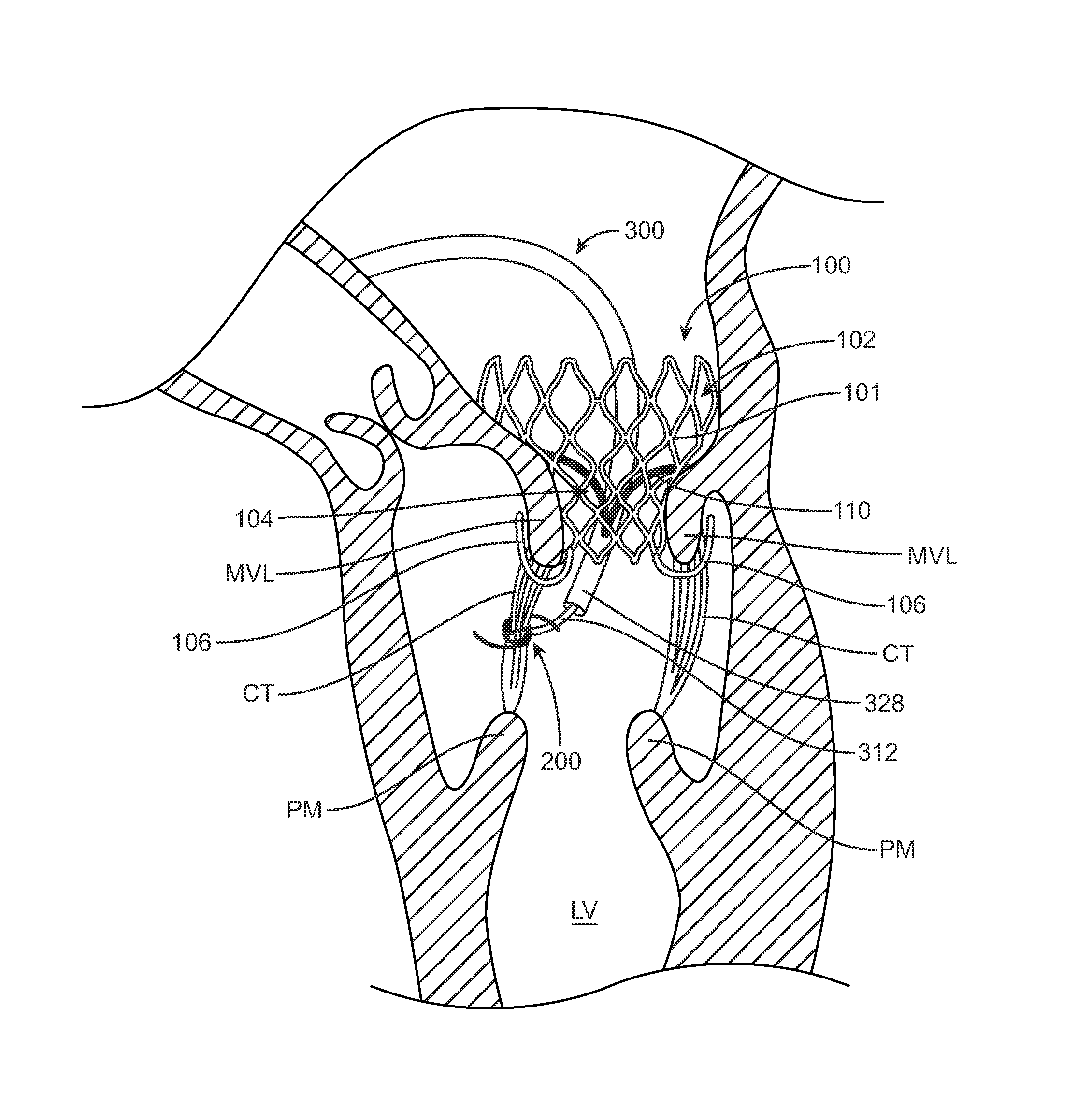
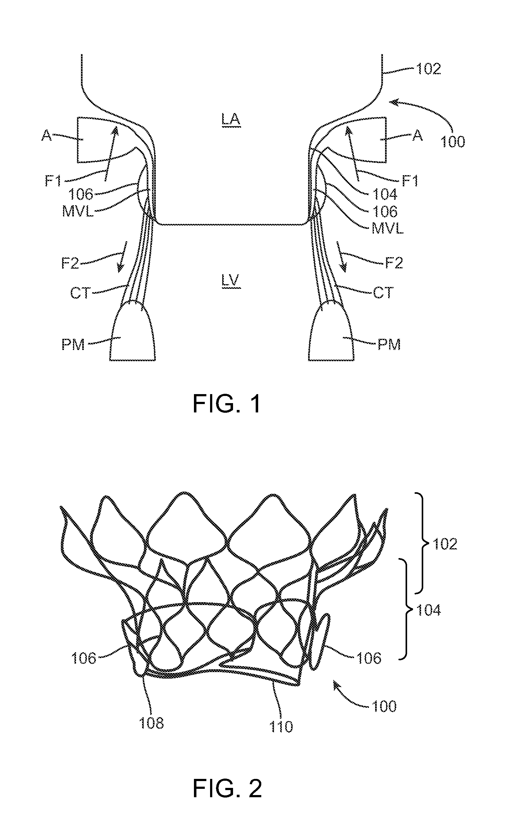
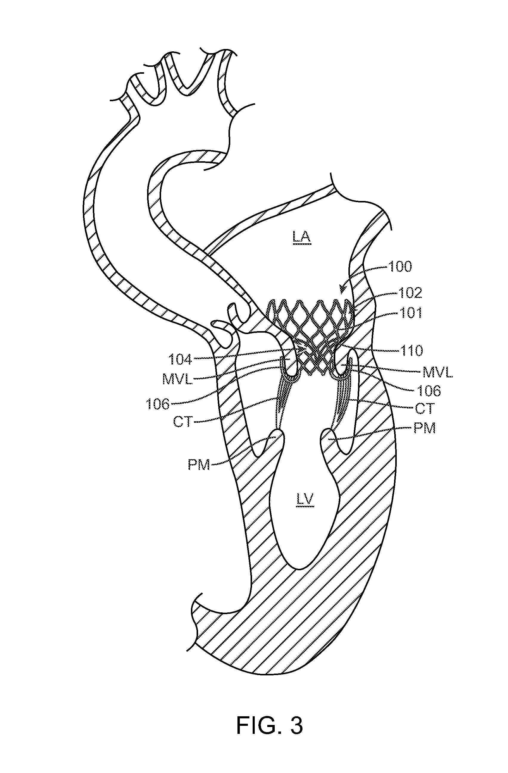
[0018]Specific embodiments of the present invention are now described with reference to the figures, wherein like reference numbers indicate identical or functionally similar elements. The terms “distal” and “proximal” are used in the following description with respect to a position or direction relative to the treating clinician. “Distal” or “distally” are a position distant from or in a direction away from the clinician. “Proximal” and “proximally” are a position near or in a direction toward the clinician. In addition, as used herein, the terms “outward” or “outwardly” refer to a position radially away from a longitudinal axis of the stent and the terms “backward” or “backwardly” refer to the relative transition from a distal position to a proximal position.

[0019]The following detailed description is merely exemplary in nature and is not intended to limit the invention or the application and uses of the invention. Although the description of the invention is in the context of tre...


PUM


Abstract

A method for treating paravalvular leakage at a location of a stented prosthetic valve includes the steps of delivering a clip to a location adjacent chordae tendinae of a native valve, and deploying the clip such that the clip captures at least some of the chordae tendinae of the native valve, thereby increasing tension in the captured chordae tendinae. The clip is delivered to the location in a collapsed stated and is released from a sheath convert to an undeflected or relaxed state. After the clip is released from the sheath, the clip is rotated to capture the chordae tendinae. The clip is then released from the delivery system and the delivery system is retracted.

Description

FIELD OF THE INVENTION[0001]The present invention is directed to devices and method for treating paravalvular leakage after implantation of a stented prosthetic valve.BACKGROUND OF THE INVENTION[0002]A human heart includes two atrio-ventricular valves through which blood flows from the atria to the ventricles, the valves functioning to prevent return of blood to the atrium. The tricuspid valve, also known as the right atrioventricular valve, is a tri-flap valve located between the right atrium and the right ventricle. The mitral valve, also known as the bicuspid or left atrioventricular valve, is a dual-flap valve located between the left atrium (LA) and the left ventricle (LV), and serves to direct oxygenated blood from the lungs through the left side of the heart and into the aorta for distribution to the body. As with other valves of the heart, the mitral valve is a passive structure in that it does not itself expend any energy and does not perform any active contractile function...

Claims


Application Information

Patent Timeline
Patent Type & Authority Patents(United States)
IPC IPC(8): A61F2/24A61B17/04
CPCA61F2/2427A61F2/2418A61B2017/0437A61F2230/008A61F2220/0075A61F2230/005A61F2230/0054A61F2/2457A61B17/1227A61B17/1285A61B2017/00243A61B2017/0409A61B2017/0441A61B2017/0464A61B2017/0496
Inventor QUILL, JASONROTHSTEIN, PAUL
Owner MEDTRONIC ARDIAN LUXEMBOURG SARL
Why Eureka
Try Eureka