
Determining building floor level of wireless mobile communication device

a wireless mobile communication and building floor technology, applied in wave based measurement systems, navigation instruments, instruments, etc., can solve problems such as uncertainty and ambiguity, and the knowledge of the elevation of wireless mobile communication devices may not be sufficient to enabl

Active Publication Date: 2015-03-24
CELLCO PARTNERSHIP INC
View PDF12 Cites 27 Cited by
  • Summary
  • Abstract
  • Description
  • Claims
  • Application Information

AI Technical Summary

Benefits of technology

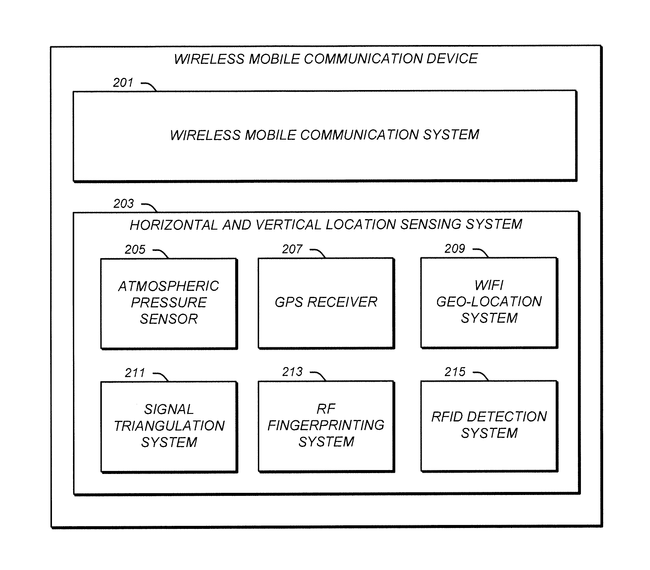
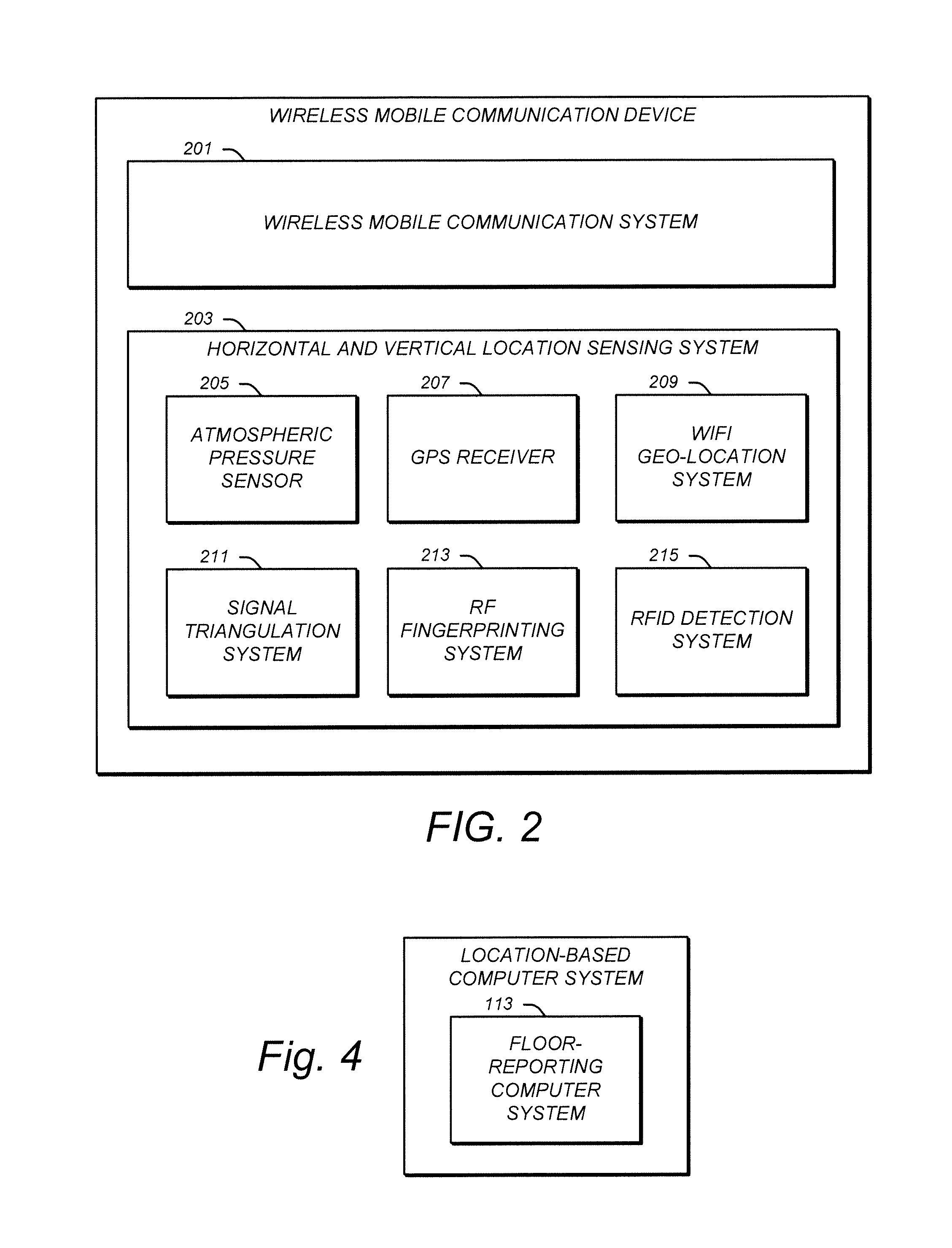
The invention is a floor-reporting computer system that can determine the specific floor on which a wireless mobile device is located in a building. This is accomplished through a network interface that receives device location information from a network communication system that originated from the wireless mobile device. The computer processing system then uses this information to determine floor location information that indicates the specific floor on which the wireless mobile device is located. The floor-reporting computer system can be used in location-based and emergency response computer systems to provide location-based services and aid in emergency response efforts.

Problems solved by technology

Unfortunately, systems which determine the location of wireless mobile communication devices may focus only on the horizontal location of the device.
This can create uncertainties and ambiguities when the wireless mobile communication device is located on a particular floor of a multi-floor building.
Even knowledge of the elevation of the wireless mobile communication device may not be sufficient to enable the location of the wireless mobile communication device within the multi-floor building to be determined.

Method used


Image

  • Determining building floor level of wireless mobile communication device
  • Determining building floor level of wireless mobile communication device
  • Determining building floor level of wireless mobile communication device

Examples


Embodiment Construction

[0024]Illustrative embodiments are now described. Other embodiments may be used in addition or instead. Details which may be apparent or unnecessary may be omitted to save space or for a more effective presentation. Some embodiments may be practiced with additional components or steps and / or without all of the components or steps which are described.

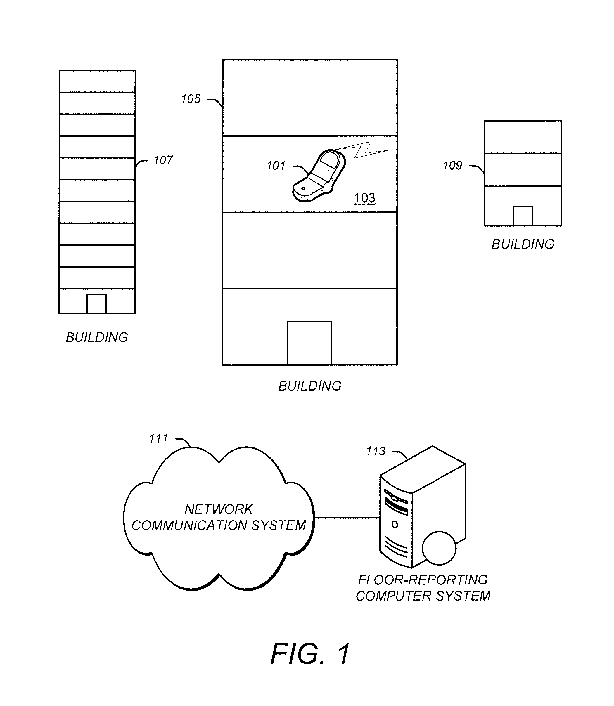
[0025]FIG. 1 illustrates an example of various multi-floored buildings, a wireless mobile communication device on an upper floor of one of the buildings, a network communication system, and a floor-reporting computer system. As illustrated in FIG. 1, a wireless mobile communication device, such as a cell phone 101, may be located on one floor of a building, such as on the third floor 103 of a building 105. Other buildings may be in the vicinity, such as a building 107 and a building 109. As illustrated in FIG. 1, each building may have a different number of floors and a different height for each floor.

[0026]As also illustrated in FIG. 1,...


PUM


Abstract

A floor-reporting computer system may determine the specific floor in a building on which a wireless mobile communication device is located. A network interface may receive device location information from a network communication system which originated from the wireless mobile communication device and which is indicative of the horizontal and vertical location of the wireless mobile communication device. A computer processing system may receive the device location information from the network interface and determine floor location information indicative of the specific floor in the building on which the wireless mobile communication device is located based on the device location information. The computer processing system may consult one or more databases when determining the floor location information, such as a building location database, a ground elevation database, a building floor height database, and / or an atmospheric air pressure database.

Description

BACKGROUND[0001]1. Technical Field[0002]This disclosure relates to systems and processes which need to know the location of wireless mobile communication devices, such as computer systems which provide location-based services and / or computer systems which provide responses to emergencies.[0003]2. Description of Related Art[0004]Various systems and services may need to know the location of wireless mobile communication devices, such as a cell phones.[0005]For example, a broad variety of location-based services may be provided to users of wireless mobile communication devices. To obtain these services, the wireless mobile communication device may provide information indicative of the location of the wireless mobile communication device. In turn, the location based service may provide information about products, businesses, and services within the vicinity of the wireless mobile communication device.[0006]Another example is emergency response services, such as the emergency response se...

Claims


Application Information

Patent Timeline
IPC IPC(8): G01C21/00
CPCG01C5/06G01C21/206G01S19/48G06F21/88H04W4/90H04W4/33
Inventor KOLODZIEJ, KRIS
Owner CELLCO PARTNERSHIP INC
Learn More