
Damping device for movable furniture parts

Active Publication Date: 2015-03-31
JULIUS BLUM GMBH
View PDF19 Cites 18 Cited by
  • Summary
  • Abstract
  • Description
  • Claims
  • Application Information

AI Technical Summary

Benefits of technology

The present invention aims to provide a damping device that reduces the number of components required and has a more robust structure, reducing the likelihood of trouble. Additionally, a sealing body can be included to further reduce the number of components.

Problems solved by technology

In the state of the art, a relatively large number of individual parts are necessary for the damping device, and those parts, due to the desired compact structure of furniture dampers, are additionally very small and delicate, in which respect assembly of the damper is also relatively complicated and laborious.

Method used


Image

  • Damping device for movable furniture parts
  • Damping device for movable furniture parts
  • Damping device for movable furniture parts

Examples


Embodiment Construction

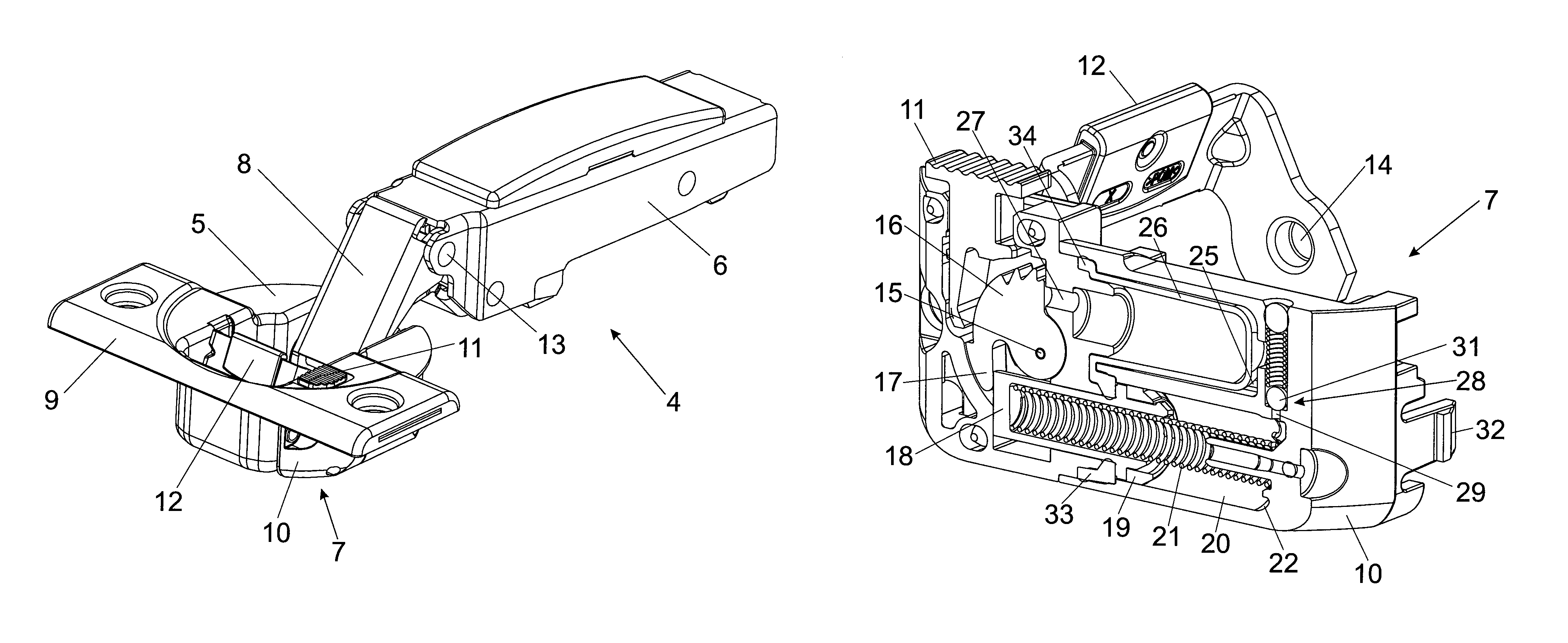
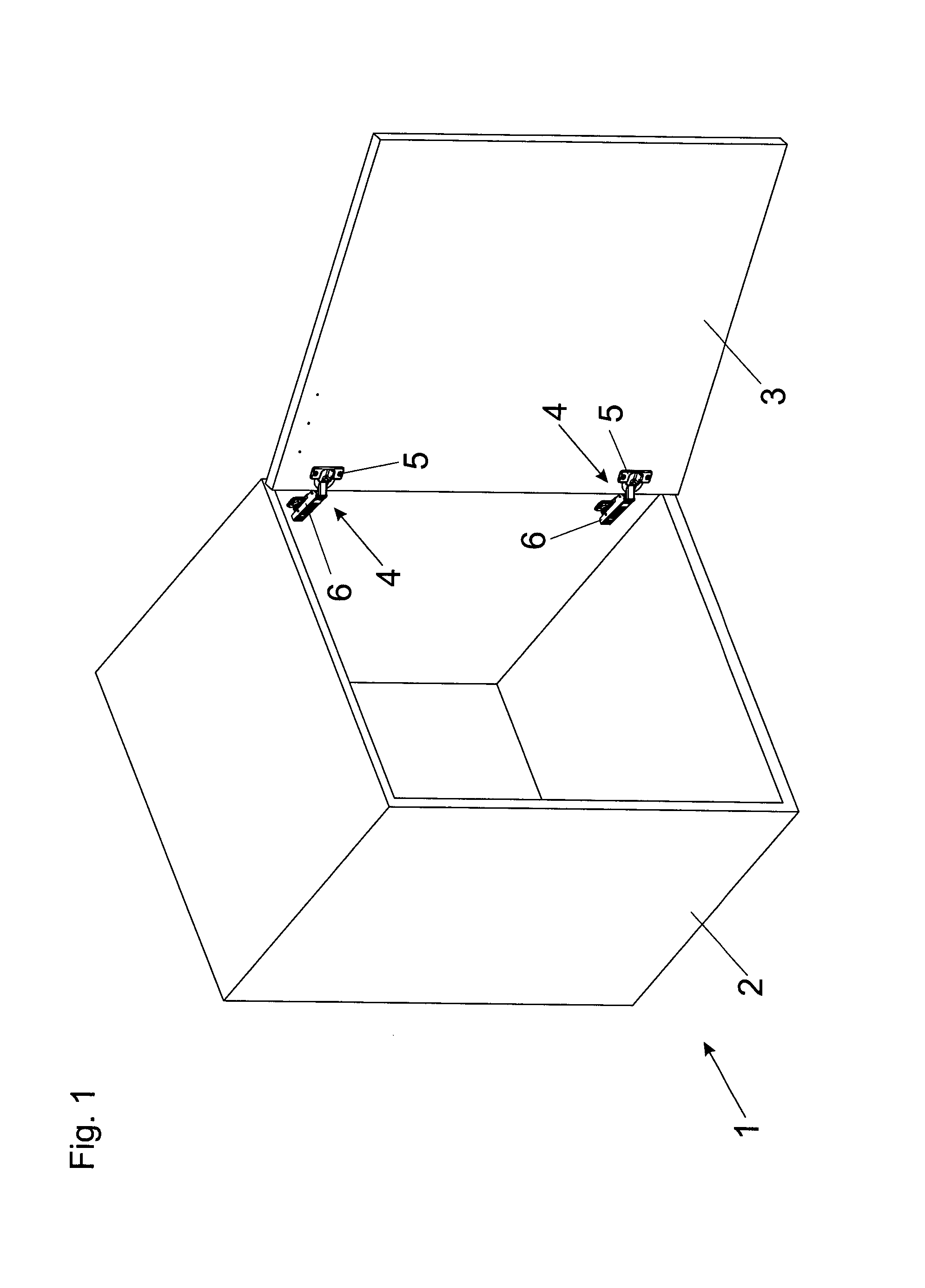
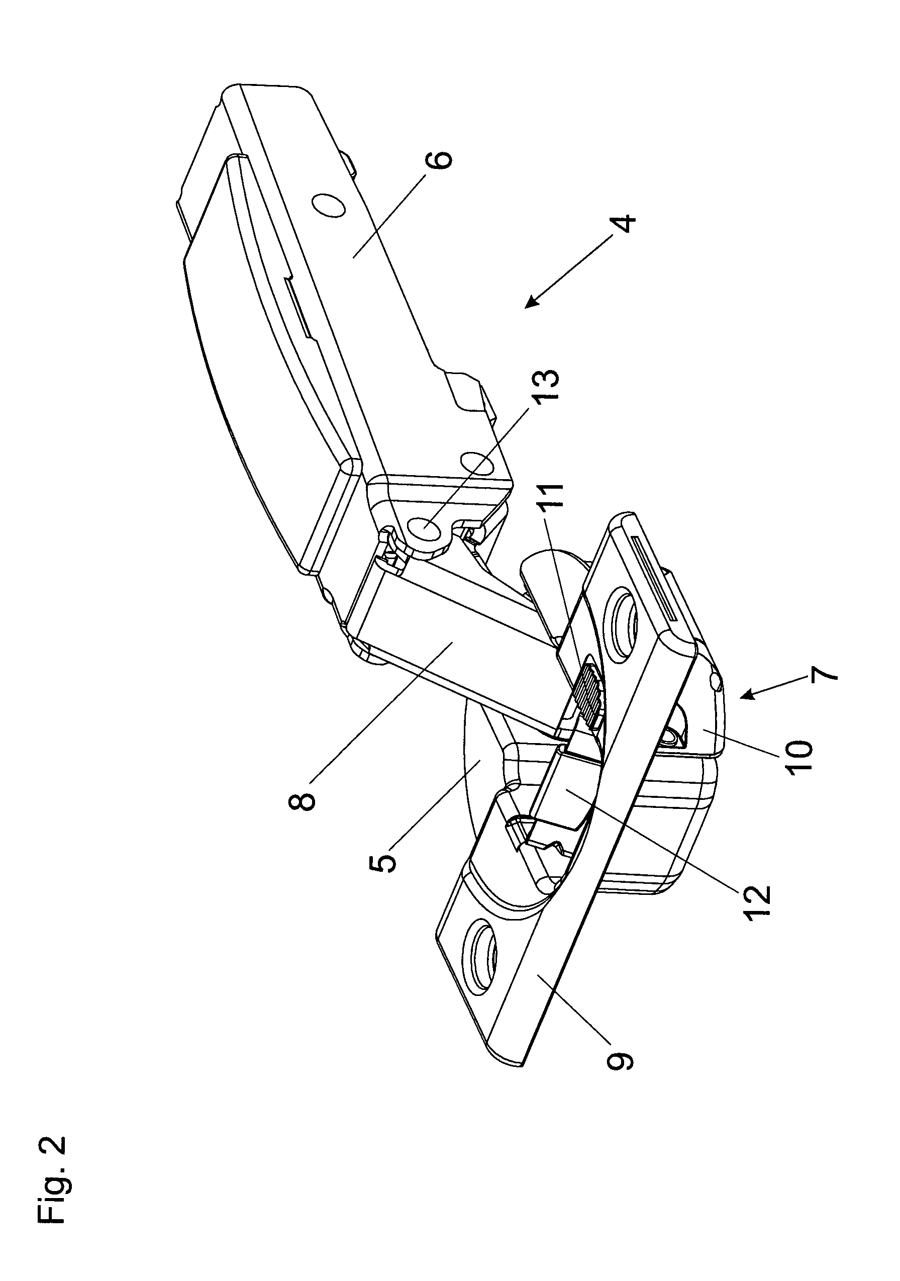
[0027]FIG. 1 shows a perspective view of an article of furniture 1, wherein a door 3 is mounted pivotably by way of furniture hinges 4 relative to a furniture carcass 2. In a known manner, the furniture hinges 4 have a hinge cup 5 hingedly connected to a carcass-side fitment portion in the form of a hinge arm 6. The furniture hinges 4 each have a damping device 7 (not visible here) for damping a hinge movement, and it is preferably provided that the damping device 7 is mounted in or on the hinge cup 5. In particular it can be provided that at least one damping device 7 is mounted to the outside of the hinge cup 5, wherein the hinge cup 5 together with at least one damping device 7 arranged thereon can jointly be fitted within a provided furniture standard bore in the door 3 and are arranged within a notional diameter of the bore.

[0028]FIG. 2 shows a perspective view of a furniture hinge 4, wherein the hinge cup 5 is pivotably connected to the hinge arm 6 by way of at least one hinge...


PUM


Abstract

A damping device for movable furniture part, includes a damper housing, a fluid chamber which is arranged in the damper housing and in which a piston is movably mounted, a tappet which is connected to the piston, at least one seal being arranged between the damper housing and the tappet in order to seal the fluid chamber, wherein the tappet passes through the seal, a compensating chamber which is fluidically connected to the fluid chamber, which runs laterally parallel to the fluid chamber. At least one deformable compensating body is arranged in the compensating chamber in order to compensate for a volume change due to the tappet being immersed into the fluid chamber. The deformable compensating body and the at least one seal are designed together as a single piece.

Description

BACKGROUND OF THE INVENTION[0001]The present invention concerns a damping device for moveable furniture parts, comprising:[0002]a damper housing,[0003]a fluid chamber arranged in the damper housing and in which a piston is moveably supported, and[0004]a ram connected to the piston. Arranged between the damper housing and the ram is at least one seal for sealing off the fluid chamber, and the ram passes through the seal.[0005]In addition, a compensating chamber which is in fluid-conducting relationship with the fluid chamber extends laterally parallel to the fluid chamber and there there is arranged at least one deformable compensating body in the compensating chamber for compensation for a change in volume due to the ram immersing into the fluid chamber.[0006]The damping action of fluid dampers is substantially based on the flow resistance of a damping fluid present in a fluid chamber. When the piston is subjected to pressure, it is displaced relative to the fluid chamber, in which ...

Claims


Application Information

Patent Timeline
IPC IPC(8): E05D11/10E05F3/04E05F3/10E05F3/20E05F5/00E05F5/02F16F9/08F16F13/00
CPCE05F3/20E05F5/006E05F5/02E05F3/04E05F3/10F16F9/08F16F13/007E05Y2201/21E05Y2201/254E05Y2201/264E05Y2900/20E05Y2201/214E05Y2201/22E05F5/00
Inventor BRUNNMAYR, HARALD
Owner JULIUS BLUM GMBH
Learn More