Locking connector

a technology of locking connectors and connectors, applied in the direction of threaded fasteners, screw connections, coupling devices, etc., can solve the problems of post turning and loosening its own mounting, affecting the service life of the connector, etc., to achieve the effect of easy adaptability to other connector types or families

Active Publication Date: 2015-03-31
MICRO COAX
View PDF24 Cites 29 Cited by
  • Summary
  • Abstract
  • Description
  • Claims
  • Application Information

AI Technical Summary

Benefits of technology

[0015]A further embodiment of the invention provides a constitutive, electrical and environmental connector that successfully integrates complementing D-flats between the mating connector body and a counter bored sleeve utilizing a canted coil spring and an interlocking toothed structure that effectively allows the nut and sleeve to be self-contained when locked to the mating connector.
[0016]Embodiments of the present invention make it possible to provide a “true” self-locking connector that overcomes or mitigates some or all of the various disadvantages described above.
[0017]Embodiments of the present invention can be used very effectively in low profile applications, including right angle connectors with low profiles, and are easily adaptable to other connector types or families.
[0018]Additionally, many embodiments of the present invention allow the second body to rotate when the sleeve is in the locked position without losing its ability to seal. This allows torsion stress to be relieved without compromising the integrity of the sealed interface.

Problems solved by technology

It is well known that connectors used on satellites, military aircraft, and missile systems experience several Gs of shock and high amplitudes of vibration, which can cause the nuts to loosen, which degrades signal performance.
The tighter the nut is screwed onto the post, the more likely it is that the post will turn and loosen its own mounting.
As a result, even during system assembly, companies can incur major repair costs, because it becomes necessary to pull the subsystems out to re-tighten loosened nuts and posts.
Although such techniques have proven to be effective in some applications, they involve additional, costly assembly operations and / or additional parts.
They may also be difficult to install in crowded locations that may not be easily accessible.
Additionally, some previously proposed designs are not real “true locking” designs, because the nut is locked only to the rear of its own connector body rather than to the mating connector member.
It is time consuming, expensive, and difficult to achieve on crowed system platforms.
Although fast and easy to use, a disadvantage of this design is that it does not lock the nut 122 to the mating connector or panel 134.
One disadvantage of this design is that it requires a known spacing between the toothed face 142 of the nut 144 and the shoulder 150 to function correctly.
Mano's device is therefore not suitable for use with connector members 152 supplied by unknown third party vendors, where the length of the screw threaded portion 154 cannot be controlled.
Mano's device is therefore not suitable for use with many panel mounted connectors.
Another disadvantage of this design is that it relies on friction at the surfaces where the Belleville washer 146 rests on the shoulder 150, and may not function reliably when lubricants are present on those surfaces.
However, if the friction is sufficiently high completely to prevent rotation, the nut 144 cannot be released, so the device becomes non-cyclical.

Method used


Image

  • Locking connector
  • Locking connector
  • Locking connector

Examples


Embodiment Construction

[0036]A better understanding of various features and advantages of the present invention will be obtained by reference to the following detailed description of embodiments of the invention and accompanying drawings, which set forth illustrative embodiments that utilize particular principles of the invention.

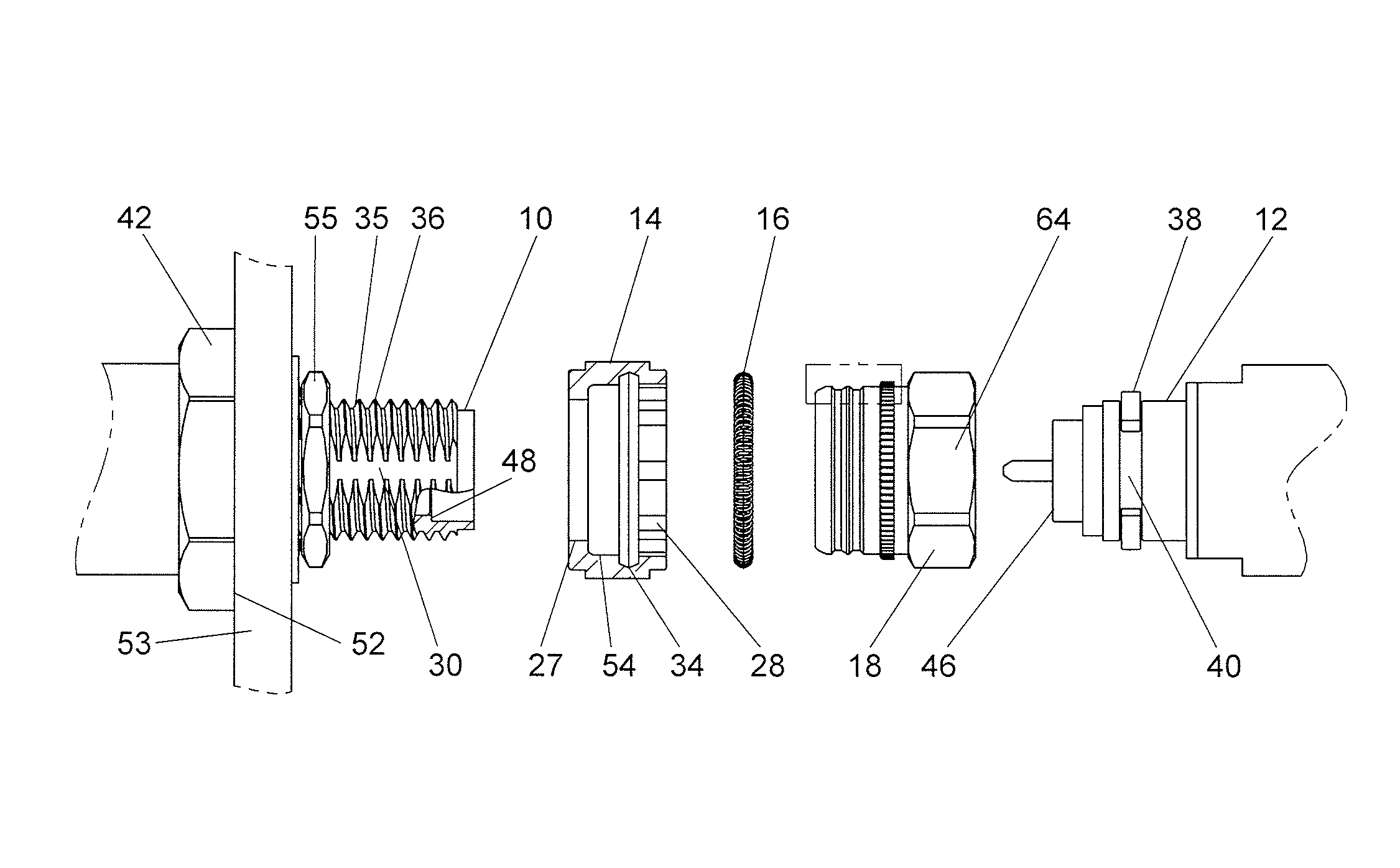
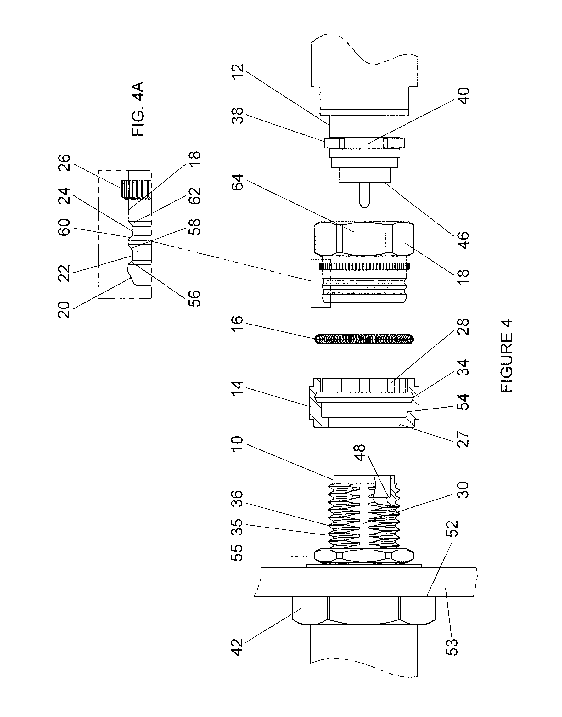
[0037]Referring to FIGS. 4 to 7A, and initially to FIG. 4, one embodiment of a connector for a coaxial cable according to an embodiment of the invention comprises a first body or connector member 10 having a threaded distal end 35 with at least one keyway in the form of a D-flat 30 axially along the threads 36. An annular sealing surface 48 is provided in the open end of the distal end 35 of connector member 10. Connector member 10 is also provided with a hexagonal structure 42 that can be grasped by a wrench for tightening. The distal face of hexagonal structure 42 defines a shoulder 52 that abuts the rear face of a panel 53 for mounting. Connector member 10 may be secured to pa...


PUM


Abstract

A self-locking connector system has a connector member having an external thread and an axially extending keyway, and a connecting interface at a distal end. A connector body has a distal end with a connecting interface that mates with the connecting interface of the connector member. An internally threaded nut is captive on the distal end of the connector body encircling the connecting interface and is configured to screw onto the externally threaded connector member. A locking collar is dimensioned to encircle the externally threaded connector member, has at least one key dimensioned to engage in the keyway, and is movable axially on the nut between a first position in which the nut is rotatable relative to the collar and a second position in which the nut is not rotatable relative to the collar.

Description

FIELD OF THE INVENTION[0001]The invention pertains to a connector to interconnect the mating ends of connector bodies, and for holding coaxial cables and other conduits for material or data coupled together, including connecting an end of a cable or other flexible conduit to a post or other connector mounted to a solid object.BACKGROUND OF THE INVENTION[0002]It is well known to connect coaxial cables, hosepipes, and other conduits for material or data end-to-end by providing a connector member with an external screw thread on one conduit end, and an internally threaded nut rotatable but captive on a connector body at the other conduit end.[0003]It is well known that connectors used on satellites, military aircraft, and missile systems experience several Gs of shock and high amplitudes of vibration, which can cause the nuts to loosen, which degrades signal performance. The risk of loosening in use can be reduced by screwing up the nut very tightly. However, the externally threaded me...

Claims


Application Information

Patent Timeline
Patent Type & Authority Patents(United States)
IPC IPC(8): H01R13/639H01R13/622H01R13/74
CPCH01R13/622H01R13/639H01R13/746F16L19/005
Inventor SCHAFER, RALPH D.MOYER, PERRY L.
Owner MICRO COAX
Why Eureka
Try Eureka