Bone scoring device

a scoring device and bone technology, applied in the field of medical devices, can solve the problems of inconsistentness and time-consuming manual bone preparation, and achieve the effect of effectively allowing

Active Publication Date: 2012-02-23
WARSAW ORTHOPEDIC INC
View PDF6 Cites 3 Cited by
  • Summary
  • Abstract
  • Description
  • Claims
  • Application Information

AI Technical Summary

Benefits of technology

[0005]An object of the present invention is to provide a bone scoring device for scoring a bone bed prior to receiving a bone graft so as to more effectively allow the bone graft to adhere to the existing bone. The bone scoring device comprising a body, a scoring member configured to engage a bone surface and a first biasing member. The first biasing member is connected to and configured to rotate the scoring member. The scoring member being axially movable between a first, non-rotatable position, such that the scoring member is engaged with the body and a second rotatable position such that the scoring member is released from engagement with the body and freely rotatable. The free rotation of the scoring member scores the bone bed in which it is in contact to create bleeding bone and / or access the underlying marrow space and the resident cell populations of the existing bone.
[0009]In another embodiment, the compression of the shield within the body is translated into rotational energy stored in the first spring by rotating the scoring member by way of the geared section on said plunger and / or scoring member interacting with a geared section on said shield. As the shield is driven up into the body past the scoring member, rotational energy is stored in the first spring until the scoring member reaches a point where the geared section on the plunger disengages from the geared section on the shield. This allows the plunger and scoring member to rotate relative to the body and release the stored rotational energy in the first spring. These steps can be repeated over and over again as needed.

Problems solved by technology

This manual bone preparation is often time consuming and can be inconsistent.

Method used


Image

  • Bone scoring device
  • Bone scoring device
  • Bone scoring device

Examples


Embodiment Construction

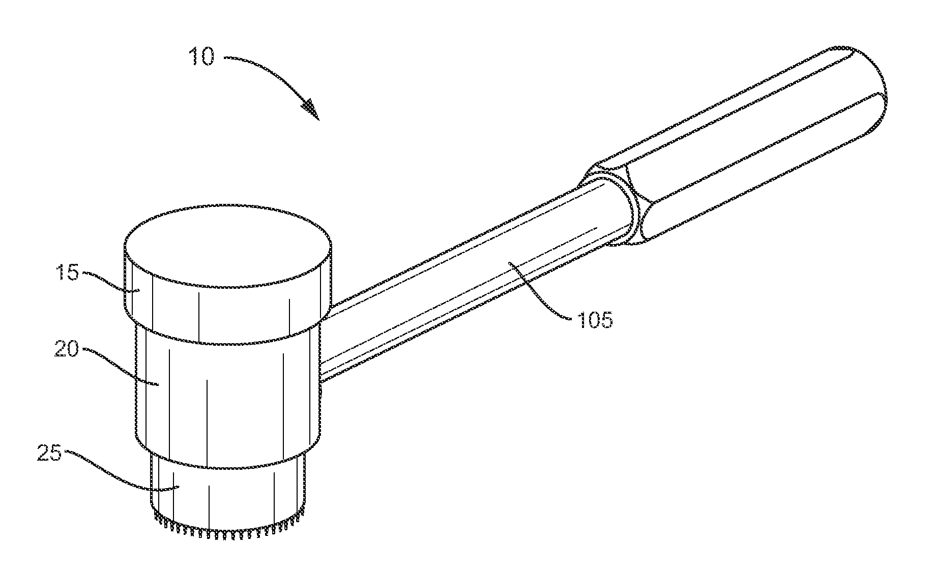
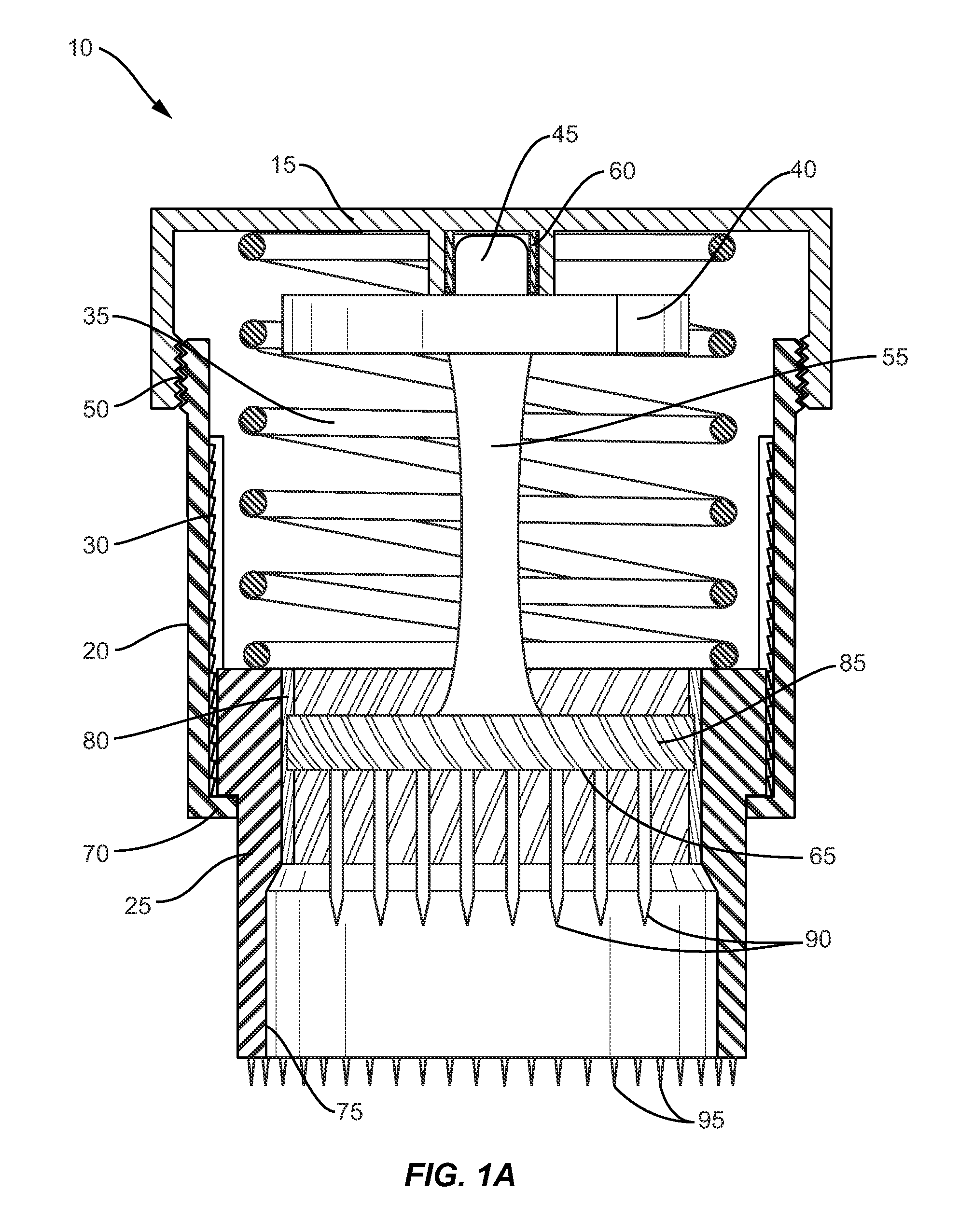
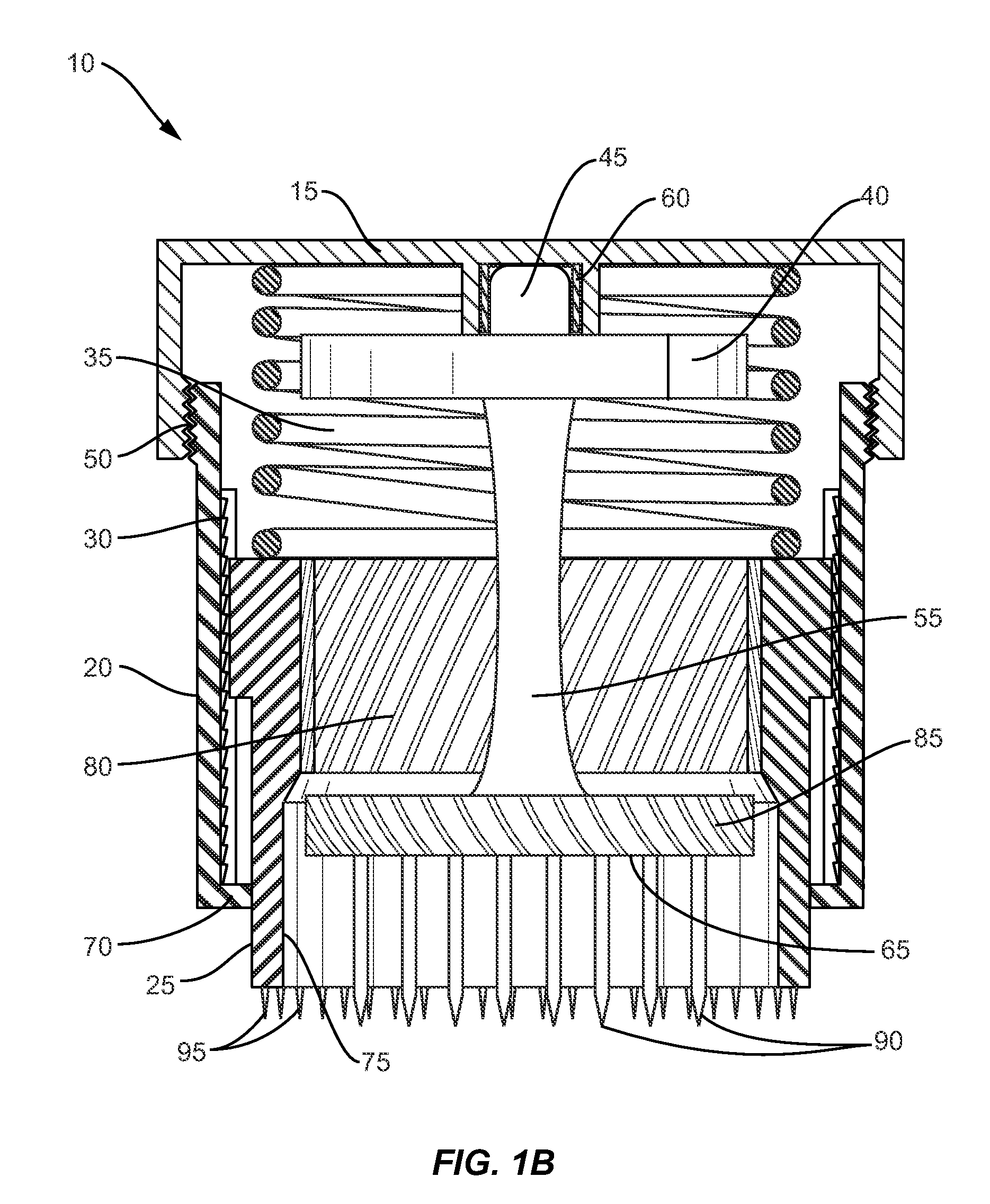
[0025]The exemplary embodiments illustrated in the Figures show a bone-scoring device of the present invention that can be used to create a consistent bone bed surface for receiving bone grafts. The scoring device of the present invention is designed to scrape or perforate the existing bone bed in a consistent manner in order to create bleeding bone and / or access the underlying marrow space and the resident cell populations of the existing bone. Once this is completed a bone graft placed on top of the scored bone bed can attach and heal more effectively.

[0026]The present invention may be understood more readily by reference to the following detailed description of the invention taken in connection with the accompanying figures, which form a part of this disclosure. It is to be understood that this invention is not limited to the specific devices, methods, conditions or parameters described and / or shown herein, and that the terminology used herein is for the purpose of describing par...


PUM


Abstract

A bone scoring device having a body, a scoring member configured to engage a bone surface and a first biasing member connected to and configured to rotate the scoring member is provided. The scoring member being axially movable between a first, non-rotatable position, such that the scoring member is engaged with the body and a second rotatable position such that the scoring member is released from engagement with the body and freely rotates. The scoring member having an abrasive surface to score the surface of the bone in which it is put in contact. A method for using the scoring device as well as a kit including the scoring device are also provided.

Description

TECHNICAL FIELD[0001]The present disclosure generally relates to medical devices for the preparation of bone for bone graft integration, and more particularly to an automated device for creating consistent bone bed surfaces.BACKGROUND[0002]Any publications or references discussed herein are presented to describe the background of the invention and to provide additional detail regarding its practice. Nothing herein is to be construed as an admission that the inventors are not entitled to antedate such disclosure by virtue of prior invention.[0003]On lay bone grafting in surgery requires preparation of the existing bone bed to encourage bone graft integration. Typical bone bed preparation involves manually scraping or perforating the existing bone bed to create bleeding bone and / or access the underlying marrow space and the resident cell populations of the existing bone. This manual bone preparation is often time consuming and can be inconsistent. Therefore, what is needed is a device...

Claims


Application Information

Patent Timeline
Patent Type & Authority Applications(United States)
IPC IPC(8): A61B17/16
CPCA61B17/1659
Inventor SHIMKO, DANIEL ANDREWDRAPEAU, SUSAN J.EMERTON, KELLY BROOK
Owner WARSAW ORTHOPEDIC INC
Why Eureka
Try Eureka