Eureka AIR delivers breakthrough ideas for toughest innovation challenges, trusted by R&D personnel around the world.

Reconstitution device

a technology of a restitution device and a retraction device, which is applied in the direction of packaging foodstuffs, packaged goods types, pharmaceutical containers, etc., can solve the problems of difficult movement of the middle stopper or the plunger for use, and achieve the effect of strong sealing, increased effective force for pushing the center stopper or the plunger, and reduced friction on the wall

Inactive Publication Date: 2015-03-31
GLUCAGO
View PDF44 Cites 4 Cited by
  • Summary
  • Abstract
  • Description
  • Claims
  • Application Information

AI Technical Summary

Benefits of technology

[0006]This unlocking may be desirable for single or multi chambered systems that change pressure during operation. In the case of a dual chambered system for a lyophilized component, the solid component may be stored under partial or full vacuum. This vacuum creates a pulling force on a middle stopper or plunger operable to urge the middle stopper to creep down into a bypass region. To account for this vacuum, the friction on the wall must be greater than the vacuum pulling force to keep the stopper or plunger in the center of the chamber. Once the dual chambered system is activated, the liquid chamber, which is commonly at atmospheric or a higher pressure, mixes with the solid component stored under the partial vacuum by flowing through a bypass or flow channel. In this scenario after the pressure in the two chambers equalize, the effective force required to push the center stopper or plunger is now greatly increased since there is no pulling force remaining from the difference in pressure between the two chambers. It will be appreciated that this may create the potential scenario where the middle stopper or plunger is too difficult to move for use with some medical applications, especially ones that require large volumes and or large diameters for the vials, cartridges, or syringes. The locking stopper described herein will maintain a strong seal and high wall friction until the stopper is activated. Once activated and advanced forward, this reduction in the wall friction will allow for easier movement in single or multi chambered systems at varying or same pressures. If a dual chamber system with different pressures in the chambers is desired, when the stopper reaches the bypass region and the pressure equalizes between the multiple chambers, this reduction of wall friction for movement will allow the stopper to be moved at a lower force than what would have been required if the stopper had the same wall friction as it did in the storage state.

Problems solved by technology

It will be appreciated that this may create the potential scenario where the middle stopper or plunger is too difficult to move for use with some medical applications, especially ones that require large volumes and or large diameters for the vials, cartridges, or syringes.

Method used


Image

  • Reconstitution device
  • Reconstitution device
  • Reconstitution device

Examples


Embodiment Construction

[0087]The following description of certain examples of the invention should not be used to limit the scope of the present invention. Other examples, features, aspects, embodiments, and advantages of the invention will become apparent to those skilled in the art from the following description, which is by way of illustration, one of the best modes contemplated for carrying out the invention. As will be realized, the invention is capable of other different and obvious aspects, all without departing from the invention. Accordingly, the drawings and descriptions should be regarded as illustrative in nature and not restrictive.

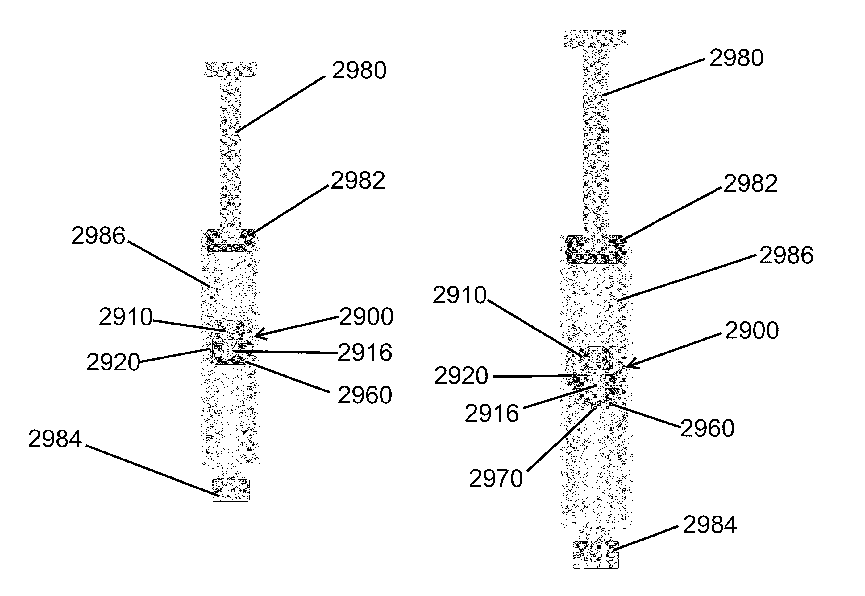
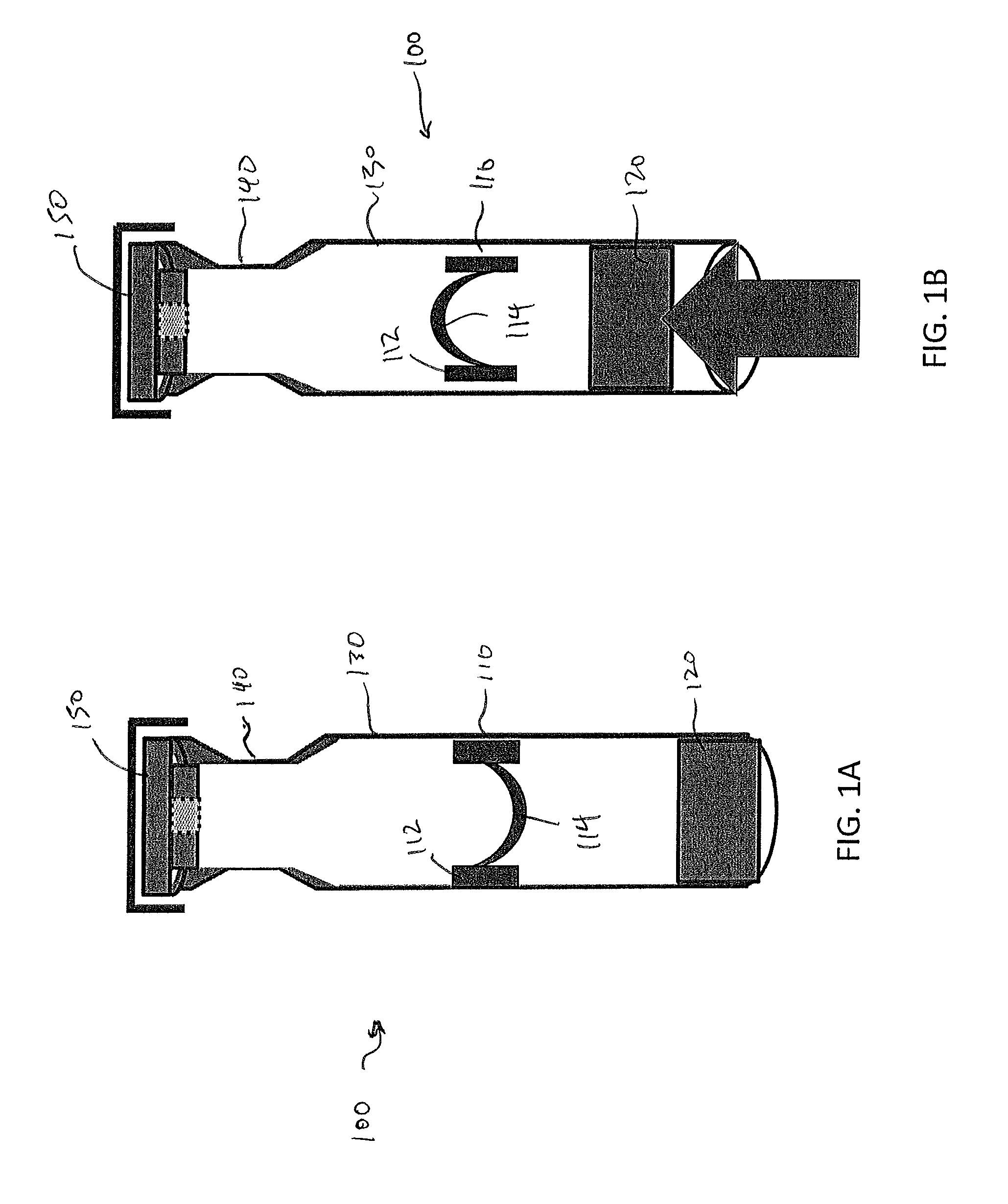
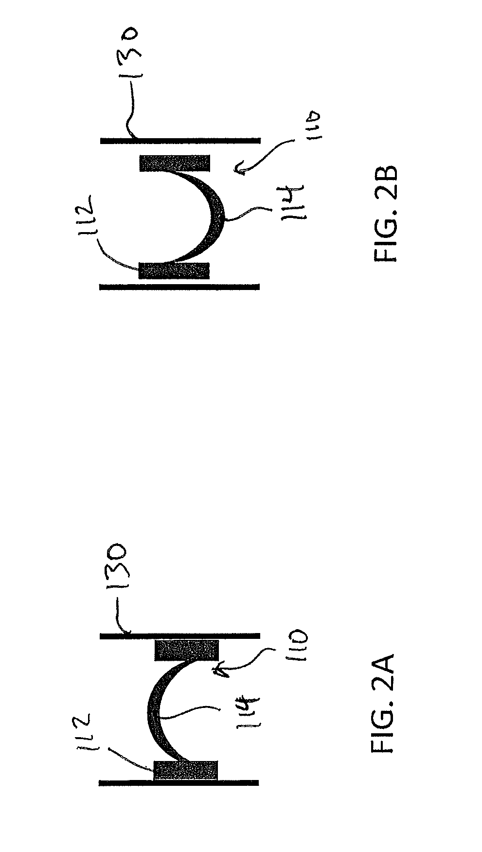
[0088]An exemplary reconstitution device, which will be described in further detail below, will be operable for use with, for instance, syringe or cartridge devices. Reconstitution device may be constructed to fit in a conventional syringe, or in other instances reconstitution device may be used with a syringe designed for use with reconstitution device. Indeed, an...


PUM


Abstract

An apparatus comprises a plunger able to fit in a cartridge or syringe. The plunger includes an outer portion and a deflection portion. The outer portion is able to engage the body of the cartridge or syringe. The outer portion is operable to apply a first radial force to the cartridge or syringe. The deflection portion is positioned within the outer portion and is movable between a locked position and an unlocked position. The deflection portion in the unlocked position causes the outer portion to apply a second radial force to the cartridge or syringe.

Description

CROSS-REFERENCE TO RELATED APPLICATIONS[0001]This application is a continuation application of PCT Serial No. PCT / US2013 / 047935, filed Jun. 26, 2013, which claims priority to U.S. Provisional Patent Application No. 61 / 664,255, filed on Jun. 26, 2012; U.S. Provisional Patent Application No. 61 / 763,651, filed on Feb. 12, 2013; and U.S. Provisional Patent Application No. 61 / 839,142, filed on Jun. 25, 2013. The disclosures of all the above-referenced patent applications are hereby fully incorporated by reference.BACKGROUND[0002]Many drugs must be stored independent of another substance (another drug or a diluent) and then mixed together in order to be administered to the patient. This administration could take place through the oral, intravenous, intradermal, intramuscular, subcutaneous, mucus membrane, skin contacting, or inhalation routes to enter the body, although this is not an exhaustive list. These medications may comprise a combination of a solid and a liquid, or a liquid with a...

Claims


Application Information

Patent Timeline
Patent Type & Authority Patents(United States)
IPC IPC(8): A61M37/00A61J1/20A61M5/315
CPCA61M5/31596A61J1/2093A61M5/3129A61M2005/3131A61M2207/00A61M2207/10
Inventor BARTLETT, II, RUSH L.GRECO, JR., PETER M.DAVIGNON, BARRY J.
Owner GLUCAGO
Why Eureka
Eureka Blog
Learn More