Apparatus and method for charging an electric vehicle

a charging device and electric vehicle technology, applied in the direction of capacitors, battery/fuel cell control arrangement, transportation and packaging, etc., can solve the problems of inefficiency, needlessly time-consuming, and inability to charge the charging device used to charge the low-voltage battery to charge the ultracapacitor, so as to reduce the overall recharge time

Active Publication Date: 2015-03-31
GENERAL ELECTRIC CO
View PDF21 Cites 59 Cited by
  • Summary
  • Abstract
  • Description
  • Claims
  • Application Information

AI Technical Summary

Benefits of technology

[0009]The invention is a method and apparatus for minimizing a total recharge time for multiple energy storage devices of an EV.

Problems solved by technology

This can lead to multiple components and charging systems because the storage devices typically cannot be charged using charging systems for other storage devices.
In other words, a charging device used to charge a low-voltage battery typically cannot be used to charge an ultracapacitor or a high-voltage battery.
Or, energy storage devices often comprise a pack or bank of storage cells that can become unbalanced in their amount of energy stored therein.
As such, during a re-charging session of all devices of an EV, re-charging the devices may be inefficient and needlessly time-consuming, overall, because one device may be preferentially charged much quicker to a full state-of-charge (SOC) while another device is charged and reaches its full SOC in a much longer time period.

Method used


Image

  • Apparatus and method for charging an electric vehicle
  • Apparatus and method for charging an electric vehicle
  • Apparatus and method for charging an electric vehicle

Examples


Embodiment Construction

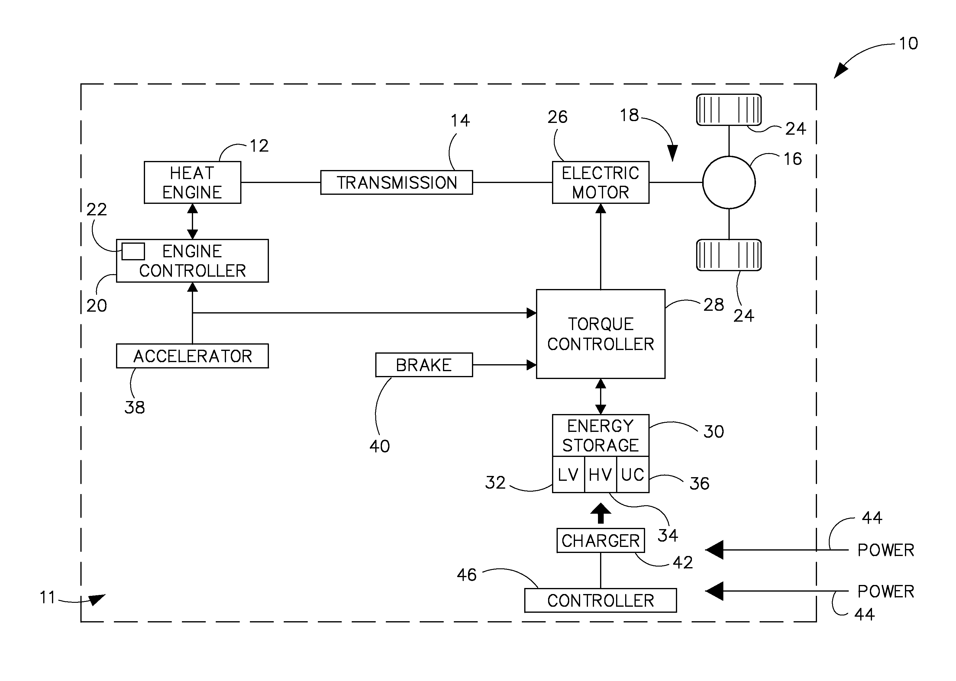
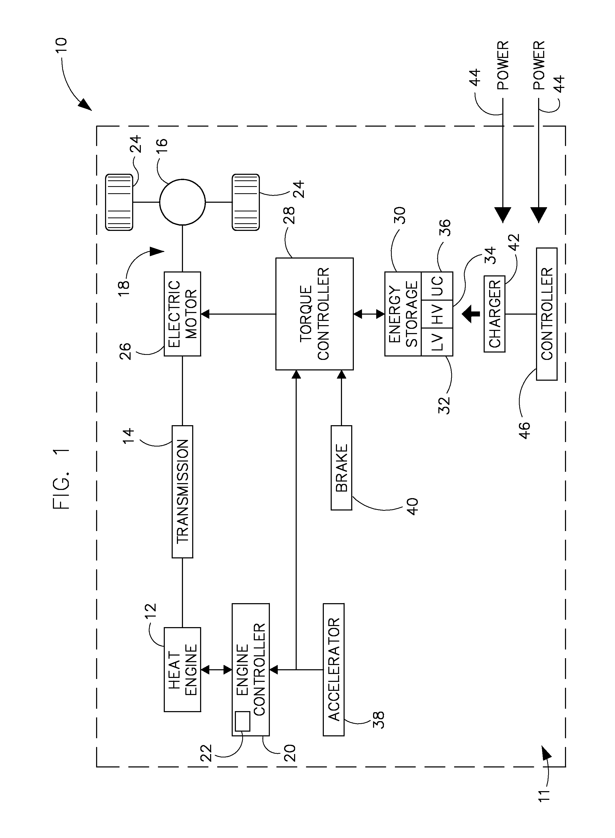
[0026]FIG. 1 illustrates one embodiment of a hybrid electric vehicle (HEV) or electric vehicle (EV) 10, such as an automobile, truck, bus, or off-road vehicle, for example, incorporating embodiments of the invention. In other embodiments vehicle 10 includes one of a vehicle drivetrain, an uninterrupted power supply, a mining vehicle drivetrain, a mining apparatus, a marine system, and an aviation system. Vehicle 10 includes an energy storage and management system (ESMS) 11 internal combustion or heat engine 12, a transmission 14 coupled to engine 12, a differential 16, and a drive shaft assembly 18 coupled between transmission 14 and differential 16. And, although ESMS 11 is illustrated in a plug-in hybrid electric vehicle (PHEV), it is understood that ESMS 11 is applicable to any electric vehicle, such as a HEV or EV or other power electronic drives used to operate pulsed loads, according to embodiments of the invention. According to various embodiments, engine 12 may be an interna...


PUM


Abstract

An energy storage and management system (ESMS) includes energy storage devices coupled to a power device, a power electronic conversion system that includes a plurality of DC electrical converters, each DC electrical converter configured to step up and to step down a DC voltage, wherein energy ports of the ESMS are coupleable to each of the energy storage devices, and each of the energy ports is coupleable to an electrical charging system. The ESMS includes a controller configured to determine a first condition of a first energy storage device and a second condition of a second energy storage device, wherein the first and second energy storage devices are each connected to respective energy ports of the power conversion system, determine a power split factor based on the first condition and on the second condition, and regulate power to the first and second energy storage devices based on the power split factor.

Description

BACKGROUND OF THE INVENTION[0001]Embodiments of the invention relate generally to electric drive systems including hybrid and electric vehicles and, more particularly, to charging energy storage devices of an electric vehicle using a multiport energy management system.[0002]Hybrid electric vehicles may combine an internal combustion engine and an electric motor powered by an energy storage device, such as a traction battery, to propel the vehicle. Such a combination may increase overall fuel efficiency by enabling the combustion engine and the electric motor to each operate in respective ranges of increased efficiency. Electric motors, for example, may be efficient at accelerating from a standing start, while internal combustion engines (ICEs) may be efficient during sustained periods of constant engine operation, such as in highway driving. Having an electric motor to boost initial acceleration allows combustion engines in hybrid vehicles to be smaller and more fuel efficient.[0003...

Claims


Application Information

Patent Timeline
Patent Type & Authority Patents(United States)
IPC IPC(8): H02J7/00B60L11/18
CPCB60L11/1864B60L11/1812B60L11/1868Y02T10/7088Y02T10/7005Y02T10/7066Y02T10/7061Y02T90/14Y02T90/127Y02T10/7072B60L2200/36B60L2200/42B60L2240/547B60L2240/527B60L2210/10Y02T10/70Y02P90/60B60L53/14B60L50/40B60L50/16B60L58/21B60L58/20Y02T10/72Y02T90/12
Inventor KUSCH, RUEDIGER SOERENKING, ROBERT DEAN
Owner GENERAL ELECTRIC CO
Why Eureka
Try Eureka