
Device and method for mounting and dismantling a component of a wind turbine

a technology for wind turbines and components, applied in the direction of electric generator control, manufacturing tools, machines/engines, etc., can solve the problems of damage to the rotor blade tip, high cost of renting, procuring and operating cranes, damage to rotor blades, etc., and achieves simple and protective mounting

Inactive Publication Date: 2015-04-07
SIEMENS GAMESA RENEWABLE ENERGY SERVICE GMBH
View PDF16 Cites 8 Cited by
  • Summary
  • Abstract
  • Description
  • Claims
  • Application Information

AI Technical Summary

Benefits of technology

The invention provides a way to easily mount and dismount wind turbine components, such as rotor blades, without using a crane. This makes maintenance and repair of the wind turbine more efficient and cost-effective. The invention includes a mounting and dismounting apparatus, a wind energy turbine, and a collar. Using these features, wind turbines can be more easily maintained without shutdowns, reducing downtime and improving reliability.

Problems solved by technology

In wind turbines damage to the rotor blades can occur, e.g., by lightning strike, corrosion or hail.
However, the known processes have the disadvantages of the high expense for renting, procuring and removing and operating the crane.
However the process has the disadvantage that the rotor blade is delivered horizontally to the ground and therefore the rotor blade must first be brought into a vertical position.
This can result in damage to the rotor blade tip when it is drawn over the ground.
Furthermore, there is the danger that the rotor blade transported close to the tower strikes against the tower in a strong wind.

Method used


Image

  • Device and method for mounting and dismantling a component of a wind turbine
  • Device and method for mounting and dismantling a component of a wind turbine
  • Device and method for mounting and dismantling a component of a wind turbine

Examples


Embodiment Construction

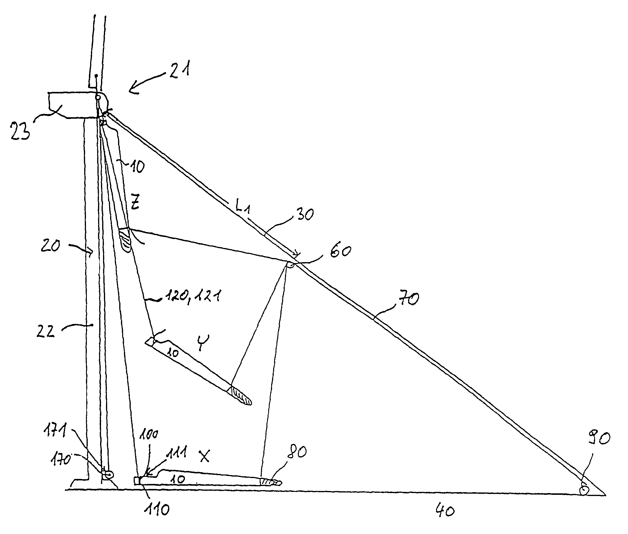
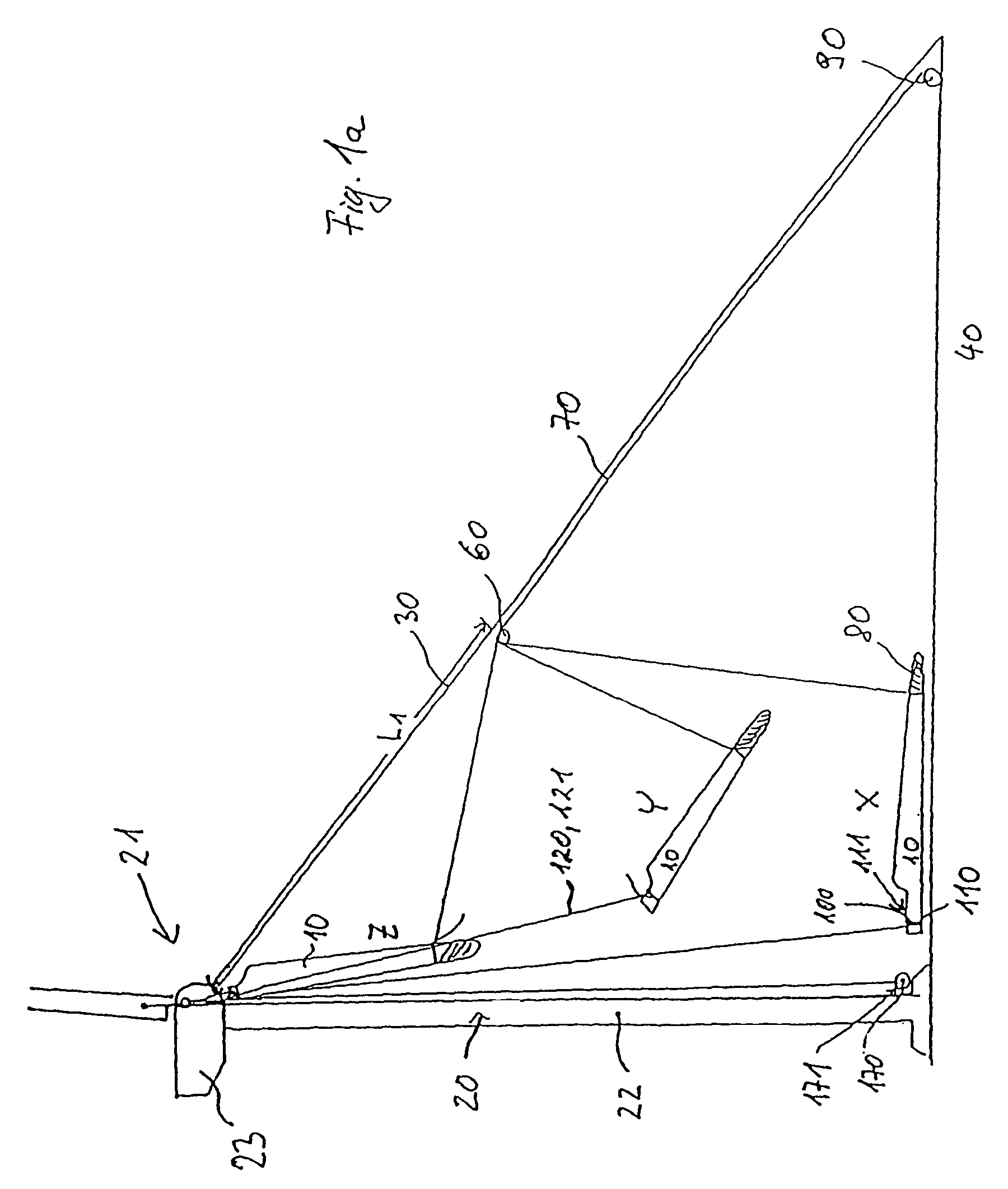
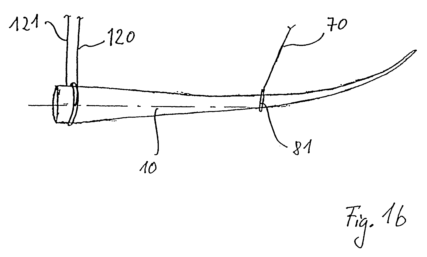
[0012]The invention makes use of the concept of making a holding apparatus available that is preferably stationary on the guide cable for mounting and / or dismantling and from which a holding cable for the component runs with the aid of which the component is transported. It is advantageous if the end of the holding cable is fastened to the component or the holding cable is reeved into a deflection roller arranged on the component. In the second embodiment the holding cable is advantageously guided back to the guide means, preferably to the holding apparatus, and its end fastened to the tower head. The holding apparatus assumes quasi a part of the traditional crane function.

[0013]The guide means is advantageously tensioned obliquely between the tower head and the ground. In a preferred embodiment of the invention the guide means is designed as a rigidly tensioned guide cable so that the position of the holding apparatus remains stationary or fixed even under the tractive load of the ...


PUM

PropertyMeasurementUnit
angleaaaaaaaaaa
lengthaaaaaaaaaa
heightaaaaaaaaaa

Abstract

The invention relates to a device for mounting and / or dismantling a component (10), in particular a rotor blade of a wind turbine (20) comprising a tower head (21). Said device comprises at least one guide element (30) that stretches between the tower head (21) and the ground (40) and has at least one supporting device (60) that is essentially fixed in the air, supporting at least a partial load of the weight of the component (10) during the transport of the latter (10) between the ground (40) and the wind turbine (20). At least one guy (70) leads from the supporting device (60) to the component (10), whereby the length of said guy between the supporting device (60) and the component (10) can be modified.

Description

BACKGROUND OF THE INVENTION[0001]The invention relates to an apparatus for mounting and / or dismantling a component, in particular a rotor blade, of a wind turbine and to a wind turbine and a collar (or sleeve or packing) in particular for this apparatus, as well as to a process for mounting and / or dismantling a component, in particular a rotor blade or rotor blade bearing of a wind turbine.[0002]In wind turbines damage to the rotor blades can occur, e.g., by lightning strike, corrosion or hail. The damaged rotor blades are then replaced in order to keep the downtimes of the wind turbine as low as possible.[0003]The replacement of the rotor blades takes place in a known manner with a crane. At first, the damaged rotor blade is rotated horizontally facing to one side or vertically under the rotor hub. There, the damaged rotor blade is fastened to the traction cable of the crane. All rotor blades have a flange at their root, which flange is firmly connected to flanges arranged on the r...

Claims


Application Information

Patent Timeline
Patent Type & Authority Patents(United States)
IPC IPC(8): B21K25/00B66C23/18F03D1/00F03D11/00
CPCF03D1/001F03D1/003F03D11/0008F05B2240/916Y02E10/721Y02E10/722Y02E10/728F03D13/10F03D80/50F03D80/70Y02E10/72Y10T29/4932
Inventor TREDE, ALFMIER, MATHIASFUGLSANG-PETERSEN, JOCHEN
Owner SIEMENS GAMESA RENEWABLE ENERGY SERVICE GMBH
Learn More