Nut for ball screw

a technology of ball screw and nut, which is applied in the direction of gearing, gearing details, hoisting equipment, etc., can solve the problems of inability to precisely position and failure of system positioning precision, and achieve the effect of reducing temperature, resistance and weight increment, increasing precise positioning and life of us

Inactive Publication Date: 2015-04-07
NAT FORMOSA UNIV
View PDF7 Cites 4 Cited by
  • Summary
  • Abstract
  • Description
  • Claims
  • Application Information

AI Technical Summary

Benefits of technology

[0012]The primary object of the present invention is to provide a nut for a ball screw to reduce the increment of temperature, resistance and weight, and increase precise positioning and life of use.

Problems solved by technology

When the temperature of the nut 910 is increased, the heat affects the length of the nut 910 so that it cannot be precisely positioned and the precision of positioning of the system fails.

Method used


Image

  • Nut for ball screw
  • Nut for ball screw
  • Nut for ball screw

Examples


Embodiment Construction

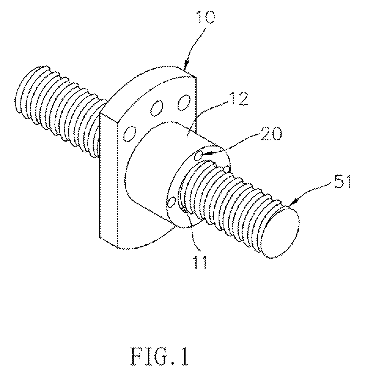
[0032]Referring to FIGS. 1, 2, 3, 4A and 4B, the present invention relates to a nut for a ball screw. It mainly comprises a nut 10, multiple dual-narrowed paths 20, multiple micro fans 30, a control portion 40, and multiple temperature sensing portions 60.

[0033]About the nut 10, it comprises an outer surface 12 and a threaded path 11 which is defined through the nut 10.

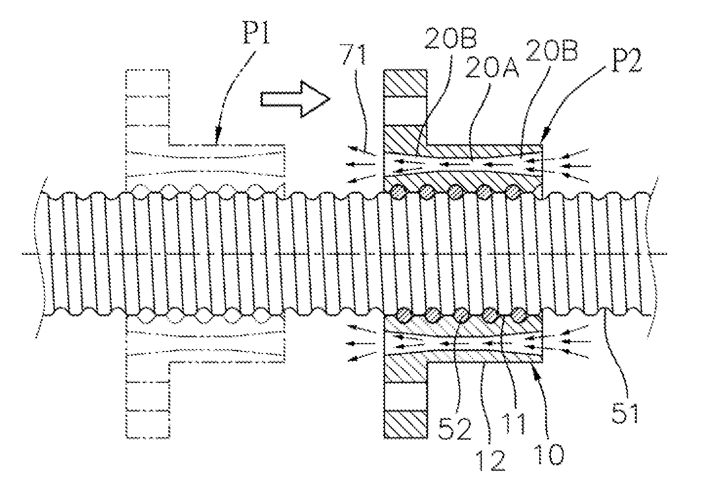
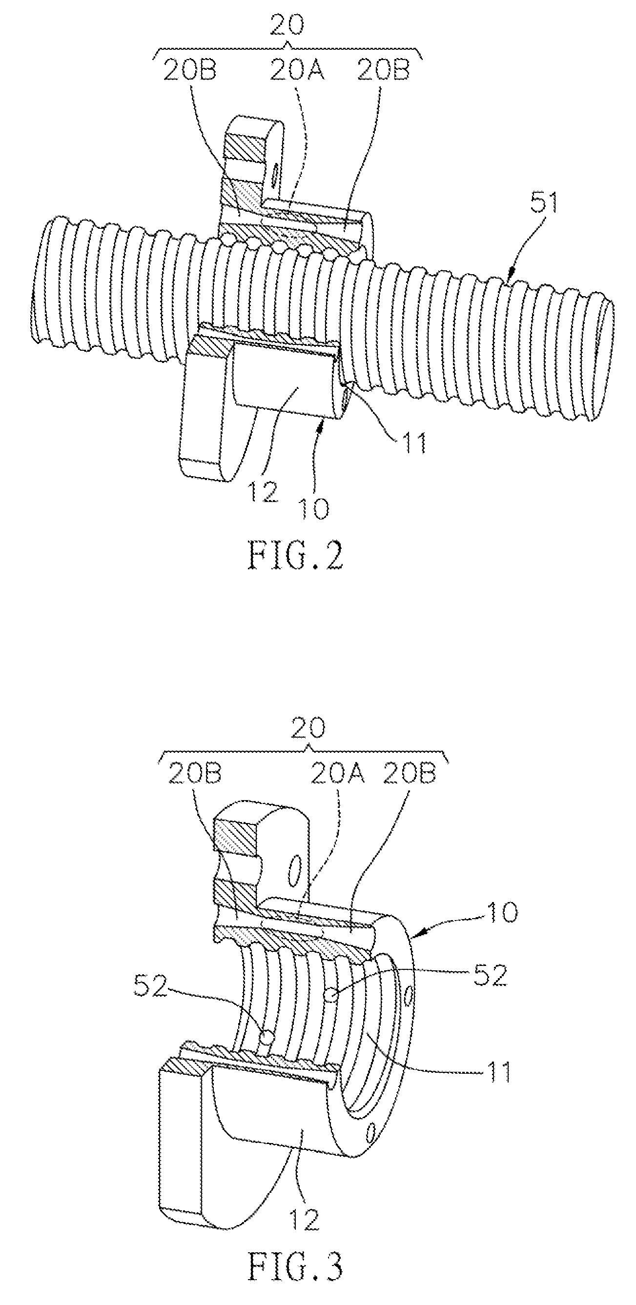
[0034]With regard to the multiple dual-narrowed paths 20, they are located between the threaded path 11 and the outer surface 12 of the nut 10, and the dual-narrowed paths 20 are defined through the central axis of the nut 10 and substantially being parallel to the threaded path 11. Each of the dual-narrowed paths 20 has a high-speed area 20A and two low-speed areas 20B, wherein the high-speed area 20A is located between the two low-speed areas 20B. The diameter of each of the dual-narrowed paths 20 is gradually reduced from two ends (the low-speed areas 20B) toward the high-speed area 20A. As shown in FIGS. 4A and 4B...


PUM


Abstract

A nut for a ball screw mainly includes a nut, multiple dual-narrowed paths, multiple micro fans, a control portion, and multiple temperature sensing portions. The nut has a threaded path and the dual-narrowed paths are defined through the central axis of the nut and substantially parallel to the threaded path. Each of the dual-narrowed paths has a high-speed area and the diameter of each of the dual-narrowed paths is gradually reduced from two ends toward the high-speed area. The nut has micro fans which drive the air flows and reduce the temperature to increase the life of use and the precision of positioning.

Description

FIELD OF THE INVENTION[0001]The present invention relates to a nut for a ball screw, and more particularly, to a nut with a dual-narrowed path so as to reduce the increment of temperature, resistance and weight, and increase precise positioning and life of use.BACKGROUND OF THE INVENTION[0002]The ball screws are used in the movable platforms of high-precision machines and are important parts for precision industry.[0003]The conventional ball screw 90 is rotated to linearly transmit a nut 910 mounted to the ball screw 90 and heat is generated during the transmission due to friction between the nut 910 and the ball screw 90. The maximum temperature is located at the center of the nut 90 wherein the balls 952 are in contact with, the maximum temperature area is designated as the max-temp area 910A. As show in FIG. 13, the temperature gradually drops from the max-temp area 910A toward two ends of the nut 910, wherein the levels of the temperature are shown by the density of the bars and...

Claims


Application Information

Patent Timeline
Patent Type & Authority Patents(United States)
IPC IPC(8): F16H25/24F16H57/04
CPCF16H25/24F16H57/0416F16H57/0497Y10T74/19702Y10T74/18712Y10T74/18736
Inventor HORNG, JENG-HAURCHEN, SHIN-YUHLIN, JEN-FINWEI, CHIN-CHUNGCHU, HSIAO-YEHCHANG, YUH-PINGLI, WANG-LONG
Owner NAT FORMOSA UNIV
Why Eureka
Try Eureka