
Wild fire and structure fire containment and barrier system

a fire containment and barrier technology, applied in fire rescue, medical science, dental surgery, etc., to achieve the effect of extending the fire-resistant barrier higher and wider, easy to transport, set up, move and tear down, and not labor or time-consuming

Inactive Publication Date: 2015-04-07
MORLIER JOHN MICHAEL
View PDF31 Cites 6 Cited by
  • Summary
  • Abstract
  • Description
  • Claims
  • Application Information

AI Technical Summary

Benefits of technology

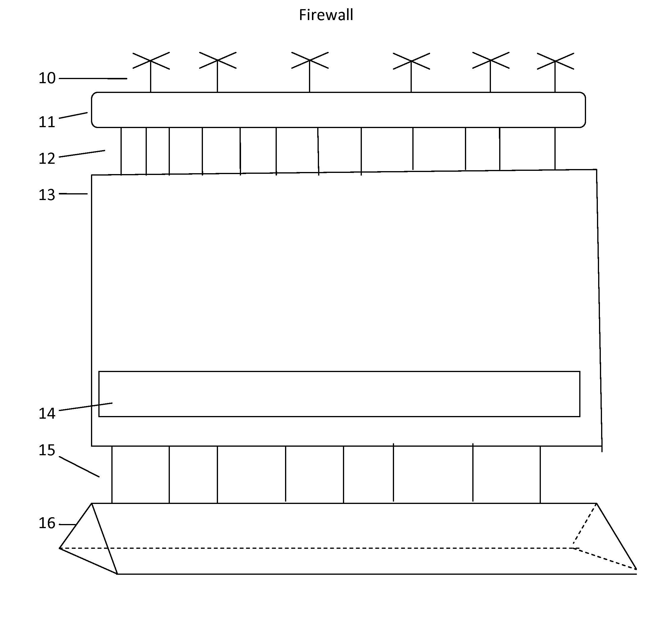
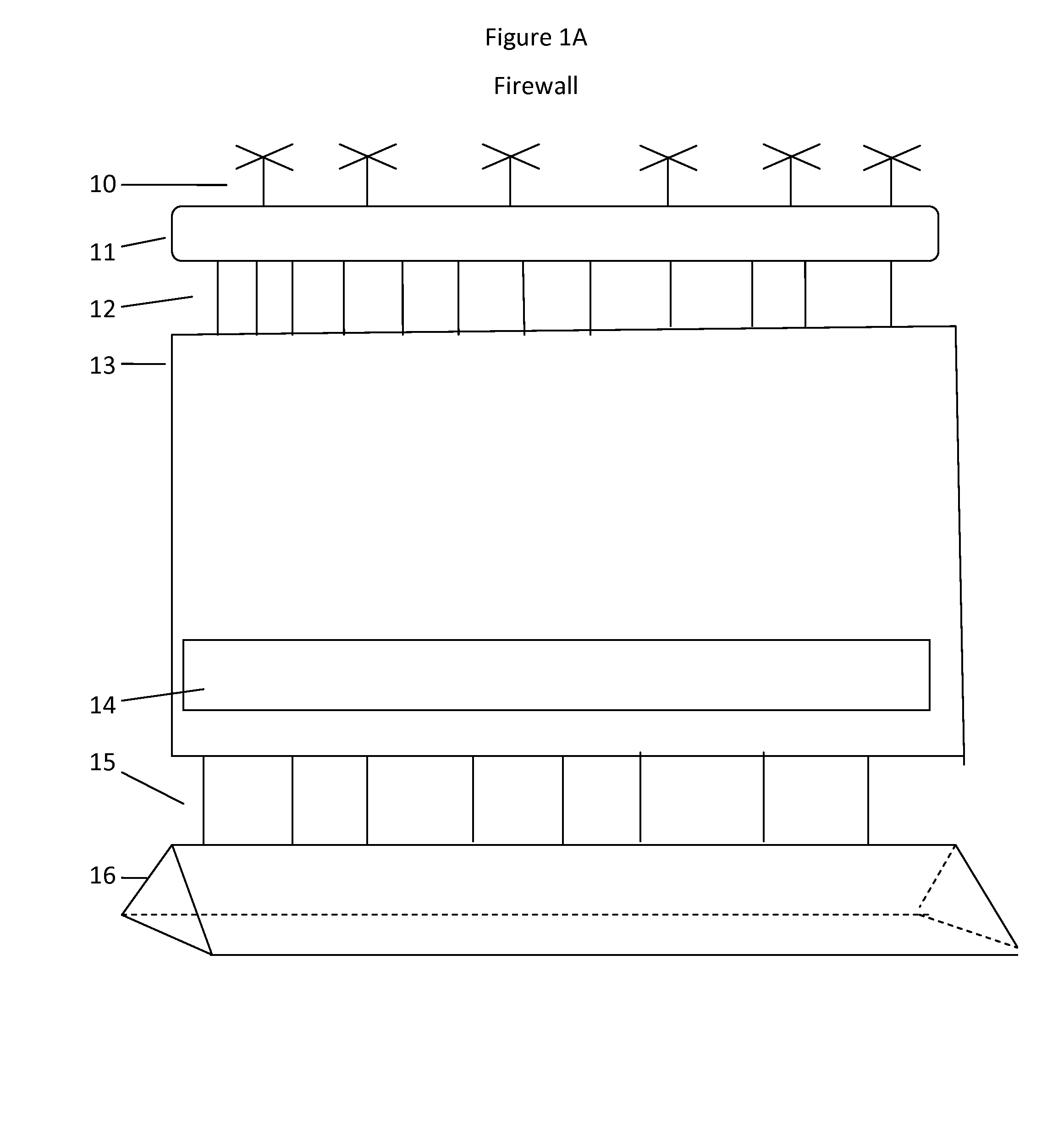
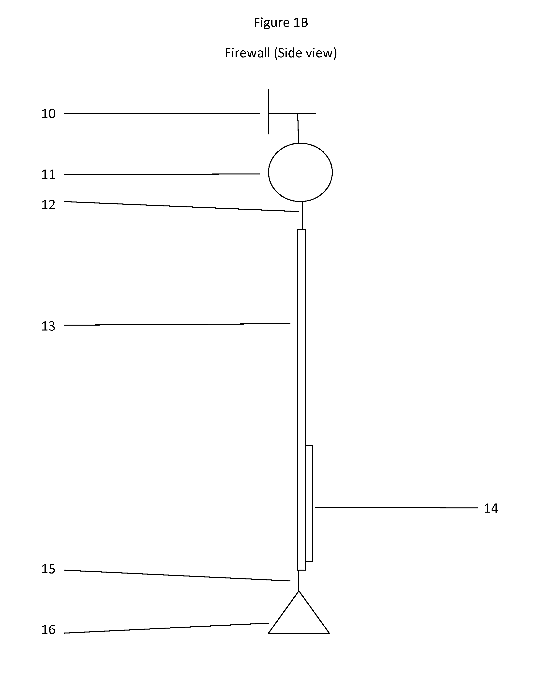
The present patent provides a fire-resistant sheet with an anchor at the bottom and a balloon along the top edge, which can be opened and closed. The sheet is connected to the balloon at the top and to the anchor at the bottom with seams or connectors. This invention provides a vertical fire barrier that can prevent fire from spreading through convection, conduction, or radiation of heat. It is lightweight, easy to transport, setup, move, and tear down. The balloon allows for dynamic positioning of the top edge and the embodiment can be extended higher and wider without coming down. The secure movable base secures the entire structure.

Problems solved by technology

However fires often jump even these fire lines.
Indeed, when a forest fire spreads to the canopies of a forest, it is called a “crown fire” and is beyond the direct control of fire fighters because of its distance from the ground.
Prior art has proposed several less effective methods to block wildfires and structure fires.
These walls are1. heavy,2. limited in height,3. difficult to transport, setup, tear down, and move,4. labor intensive to setup, move, and tear down, and5. time consuming to setup and move.6. While these walls protect a person immediately behind the wall, they do not prevent the spread of a fire due to conduction, convection, or radiation because cinders, embers, and sparks will be blown over the wall and flames will extend well above the wall.
These curtain systems exhibit the same disadvantages as the solid walls.
They are1. heavy,2. limited in height,3. difficult to transport, setup, tear down, and move,4. labor intensive to setup, move, and tear down, and5. time consuming to setup and move.6. While these curtain systems protect a person immediately behind the wall, they do not prevent the spread of a fire due to conduction, convection, or radiation because cinders, embers, and sparks will be blown over the curtain and flames will extend well above the curtain.7. Additionally they require that the bottom of the curtain be pegged to the ground, that the top of the curtain be supported by horizontal or vertical rods, and that the top of the curtain be held in fixed position by guy lines pegged into the ground at some distance on both sides of the curtain.
These requirements make the curtain barrier immobile and inflexible.
1. The bottom of the sail is fixed in place by the pegs on its bottom edge making it difficult to move.
These heat generators require combustible fuel, which may become exhausted at which point the balloon will fall.
With nowhere to go in the sail, the trapped wind will place a great pressure on the sail, thereby pushing the entire apparatus down.
However, once a sail is erected, these hooks and eyelets are inaccessible.
This makes them vulnerable to wildfire heat that can be as high as 2,192 degrees Fahrenheit.
1. By design, the membrane is pushed down by the wind and so does not prevent heat conduction, convection, or radiation from spreading the fire.

Method used


Image

  • Wild fire and structure fire containment and barrier system
  • Wild fire and structure fire containment and barrier system
  • Wild fire and structure fire containment and barrier system

Examples


first embodiment

Operation of First Embodiment

[0108]The purpose of the embodiment is to contain a wildfire or a structure fire. It creates a wall to block the spread of the fire, the cinders, the embers produced by the fire, and the heat produced by the fire. The embodiment height exceeds the height of the flames so that it can block the cinders, embers, and heat that are pushed above the flames.

[0109]The Firewall is deployed along a control line that has been cleared of fuel down to mineral soil. This is so that a fire cannot run under said Base or Anchor (16) of the Firewall. When a crew of operators brings a Firewall to a control line site, the deflated Balloon (11)(21), Seams or Connectors (12)(15), and Mesh Sheet (13) are folded and tied to the Base or Anchor (16) to form a transportable package. Said Base or Anchor (16) is pre-filled or filled on site with a heavy and fire resistant material such as, for example, sand. The folded and tied package is laid out along the control line. The package...

second embodiment

Operation of Second Embodiment

[0113]Said Propellants (10), either propellers or jets, create an air stream over said Balloons (21). Said aerodynamically shaped Balloons (21) act like airplane wings and the air stream over and under them provides additional lift to the entire structure. Said aerodynamic Balloons (21) also enhance said Propellants' (10) ability to pull said Balloons (21) and the top edge of said Mesh Sheet (13) forward.

FIGS. 3A and 3B

Detailed Description of Third Embodiment

[0114]This embodiment shows a Lip and Channel system. Each Mesh Sheet (13) will have a Lip (32) on one side edge and a Channel (31) on the opposite side edge. Said Lip (32) and Channel (31) material is fire resistant to a temperature that exceeds the temperatures found in a wildland fire or structural fire. Said Lip (32) and Channel (31) are made of light weight material, a lighter-than-air material if possible. Said Lip (32) is sized and designed to fit loosely, but securely, into said Channel (31)...

third embodiment

Operation of Third Embodiment

[0115]Firewalls can be connected by threading said Lip (32) of one Mesh Sheet (13) through said Channel (31) of an adjacent Mesh Sheet (13). Thus, Firewalls can be seamlessly added onto each other. This constitutes a means to extend the Firewall along the fire control line.

[0116]In implementation, one embodiment will already be raised and deployed. To add a second embodiment, said Lip (32) of the second embodiment, which is still at ground level, is threaded into said Channel (31) of the deployed embodiment. Then, as the second embodiment is raised, said Lip (32) of the second Firewall threads up through said Channel (31) of the first deployed embodiment. Said Lip (32) in said Channel (31) has to be loose enough so that it does not bind or snag in said Channel (31), but said Channel (31) must overlap said Lip (32) enough so that said Lip (32) does not slip out of said Channel (31). Said Channel (31) on an embodiment extends to within about a foot of the ...


PUM


Abstract

Several embodiments of a wildfire and structure fire containment system by means of a fire-resistant Mesh Sheet (13). Said Mesh Sheet (13) is held aloft by a fire resistant Balloon (11) or Balloons (21) which are filled with a lighter-than-air material comprising gas, plasma, liquid, solid, or a combination. Propellants (10) are attached to said Balloon (11) or Balloons (21). A fire resistant Base or Anchor (16) is along the bottom edge of said Mesh Sheet (13). One or more additional said Mesh Sheets (13) can be attached horizontally using a Lip (32) and Channel (31) system. Additional said Mesh Sheets (13) can be added to vertically extend the embodiment to higher elevations. A Flap (14) exists covering an opening on the bottom section of the Mesh Sheet (13). Various electronic cameras, heat sensors, wind sensors, and other electronic and digital devices can be attached.

Description

BACKGROUNDPrior Art[0001]The following is a tabulation of some prior art that presently appears relevant:[0002]U.S. PatentsPat. No.Kind CodeIssue DatePatenteeContainment and Barrier Walls  589,062Aug. 31, 1897Woodruff  951,681Mar. 8, 1910Dunlevy  973,936Oct. 25, 1910Graves4,311,199Jan. 19, 1982Elias5,944,114Aug. 31, 1999FarleyContainment and Barrier Curtains (Ground Based)2009 / 0194297A1Aug. 6, 2009TeruelContainment and Barrier Curtains (Air supported)3,635,290Jan. 9, 1972Schneider[0003]Foreign Patent DocumentsForeign Cntry.KindApp orDoc Nr.CodeCode Pub. Dt.PatenteeContainment and Barrier Walls924016FRAJul. 4, 1947Dutroy2620344FRA1Sep. 14, 1987Renoux2276543GBMar. 25, 1994Mech-Tool2124134ESJan. 16, 1999PuenteContainment and Barrier Curtains (Ground Based)561289FROct. 10, 1923Jacquement1009783FRJun. 3, 1952Leprevost2657265FRJul. 26, 1991Plantefeve2677548FRDec. 18, 1992Plantefeve1048262ESJul. 1, 2001Morgado2806636FRSep. 28, 2001Tonchia2863895FRJun. 24, 2005Tonchia200601499ESPMay 31, 200...

Claims


Application Information

Patent Timeline
IPC IPC(8): A62C8/00A62C3/00A62C2/00A62C2/04A62C2/06A62C2/10A62C2/24A62C3/02
CPCA62C2/24A62C2/10A62C3/0257A62C2/04A62C2/06
Inventor MORLIER, JOHN MICHAEL
Owner MORLIER JOHN MICHAEL
Learn More