Light reflector structure for horticultural lamps

a technology of reflectors and horticultural lamps, applied in the direction of lighting support devices, lighting and heating apparatus, saving energy measures, etc., can solve the problems of inefficient plant arrangement and inefficient mass plant growth, and achieve the effect of improving plant growth

Inactive Publication Date: 2015-04-07
ANDERSON TERRY W
View PDF20 Cites 79 Cited by
  • Summary
  • Abstract
  • Description
  • Claims
  • Application Information

AI Technical Summary

Benefits of technology

[0005]The present invention is directed to structures that reflect light for horticultural lamps to improve plant growth by intensifying the light, and by focusing light on lower branches of the plant which would be otherwise shaded by upper branches. A light reflector frame has an upper wire frame and a lower wire frame each of generally rectangular form that are spaced apart and attached at an upper peripheral edge and a lower peripheral edge by a plurality of transverse brackets. At least four of the transverse brackets have a hook formed at a top end and a bottom end such that each of the hooks opens inwardly of the upper wire frame and the lower wire frame. At least one reflective panel is disposed inwardly of at least four transverse brackets to engage the hooks with a reflective surface of each reflective panel oriented inwardly of the transverse brackets. At least two pairs of opposed transverse brackets have an extended member at the top end positioned to extend upwardly over a cover of a horticultural lamp enclosure.

Problems solved by technology

This may be inefficient for mass plant growth in situations where one light illuminates several plants.
This arrangement is not efficient for plants that principally grow vertically with multiple levels of leaf structure since the leaves further from the lamp and below upper level leaves will receive reduced light intensity.

Method used


Image

  • Light reflector structure for horticultural lamps
  • Light reflector structure for horticultural lamps
  • Light reflector structure for horticultural lamps

Examples


Embodiment Construction

[0019]The following detailed description represents the best currently contemplated modes for carrying out the invention. The description is not to be taken in a limiting sense, but is made merely for the purpose of illustrating the general principles of the invention.

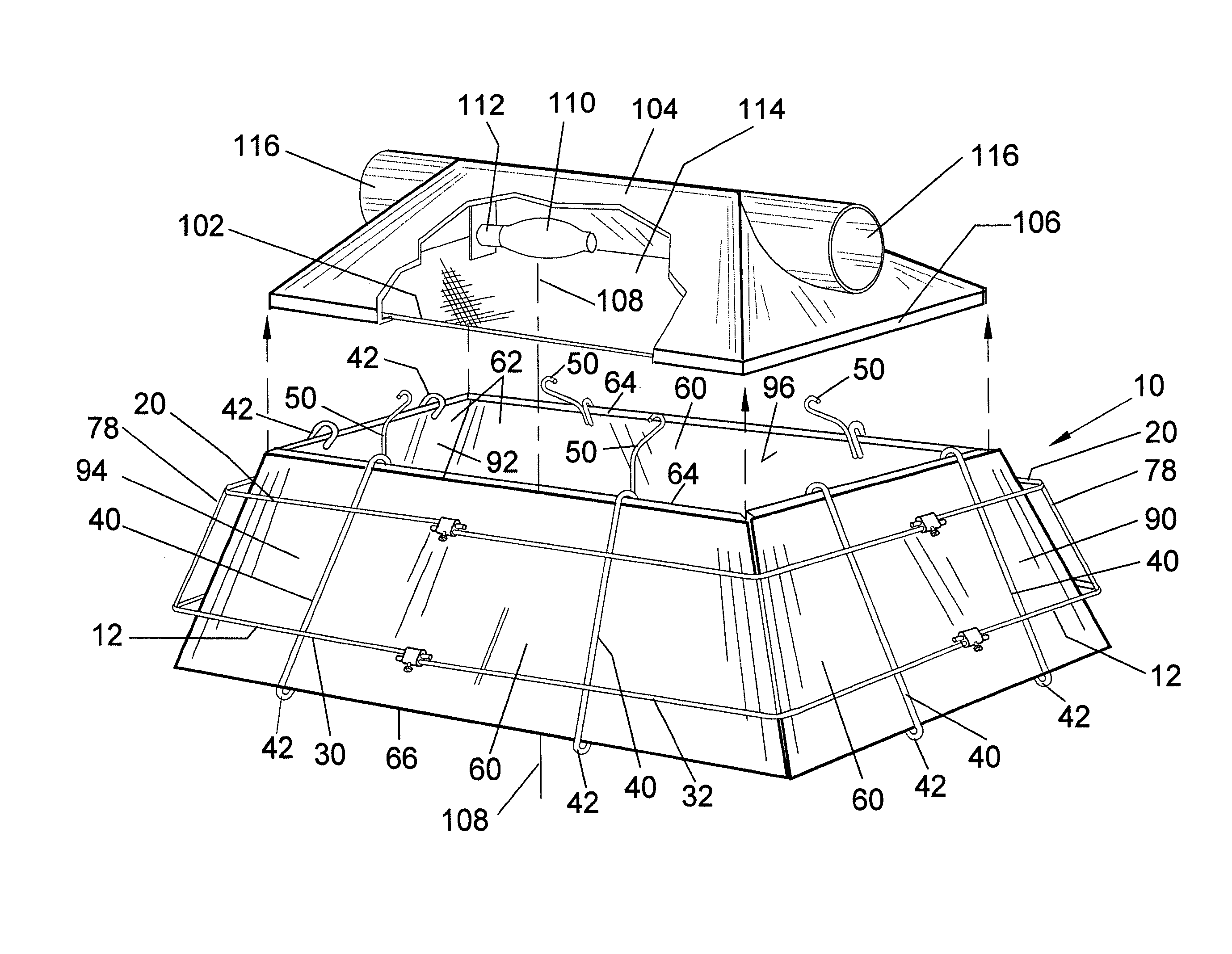
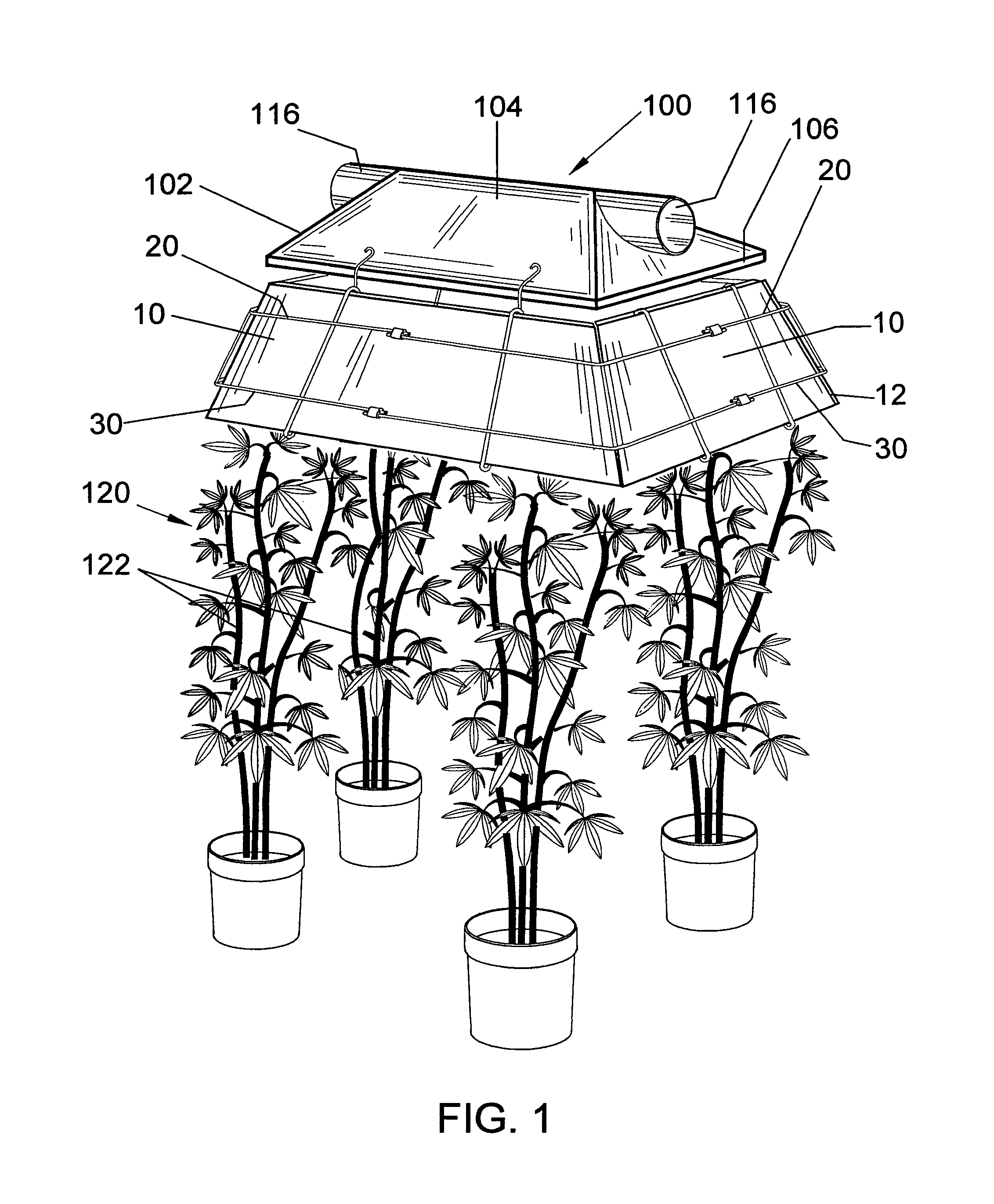
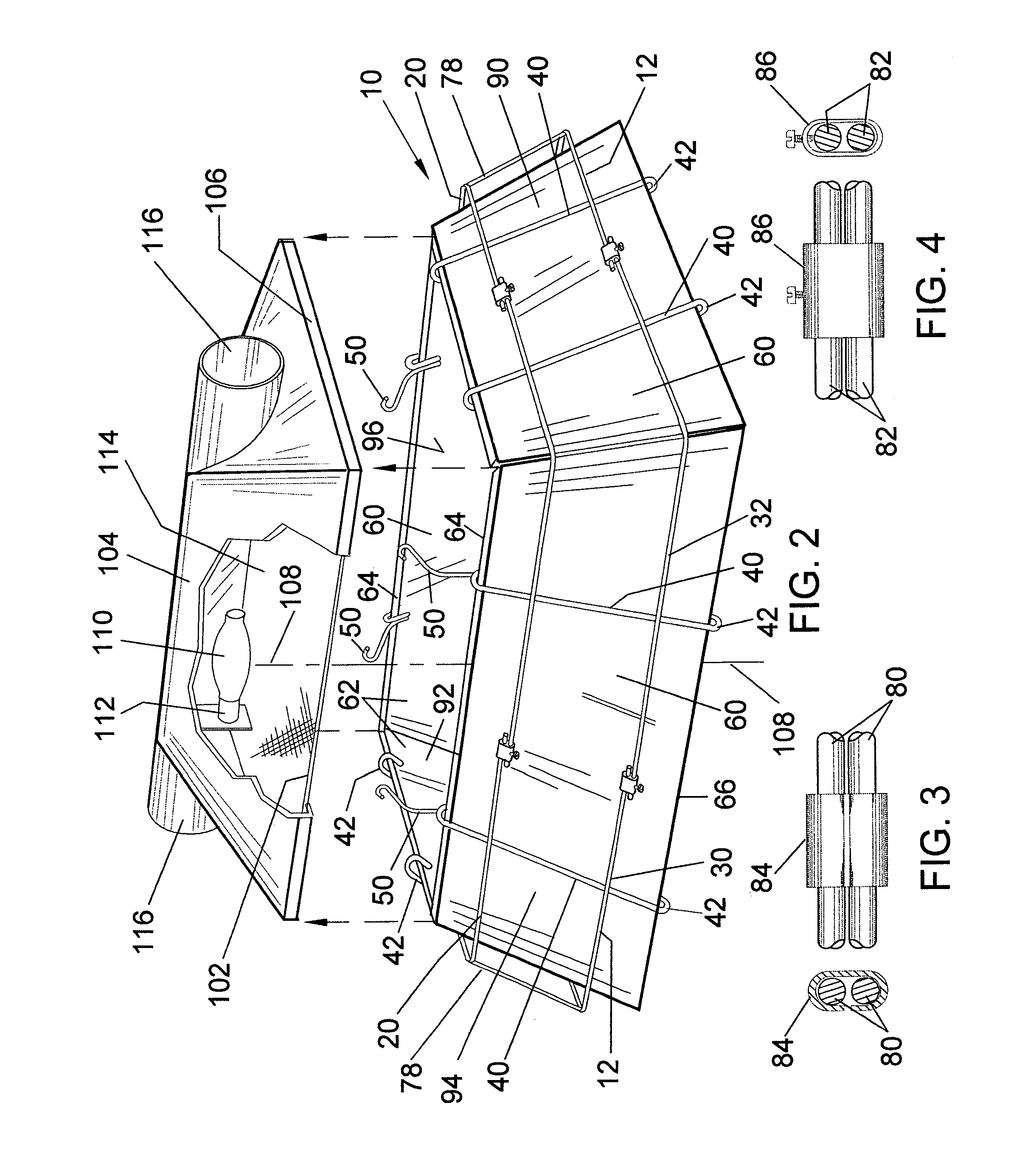
[0020]Referring to FIGS. 1 through 10, a light reflector structure 10 for a horticultural lamp 100 for enhanced plant growth for plants 120 that may grow vertically with multiple levels of leaf 122 structure may be positioned on a lamp 100 to extend downwardly from a lower peripheral edge 106 of the lamp enclosure 102 or cover 104 and may be slanted relative to the vertical center line 108 of the lamp 100, as best viewed in FIGS. 1 and 2. The lamp 100 may have a generally centrally located elongated light bulb 110 in an electrical socket 112 and the enclosure 102 may be closed at an open bottom side of the cover 104 by a generally transparent panel 114, for example, glass panel. This lamp 100 structure allows light emi...


PUM


Abstract

A light reflector frame has an upper wire frame and a lower wire frame each of generally rectangular form that are spaced apart and attached at an upper peripheral edge and a lower peripheral edge by a plurality of transverse brackets. At least four of the transverse brackets have a hook formed at a top end and a bottom end such that each of the hooks opens inwardly of the upper wire frame and the lower wire frame. At least one reflective panel is disposed inwardly of at least four transverse brackets to engage the hooks with a reflective surface of each reflective panel oriented inwardly of the transverse brackets. At least two pairs of opposed transverse brackets have an extended member at the top end positioned to extend upwardly over a cover of a horticultural lamp enclosure.

Description

BACKGROUND OF THE INVENTION[0001]This invention relates to light reflective structures for attachment to horticultural lamps to improve plant growth. The new light reflector structure extends below a horticultural lamp to reflect light emitted from the lamp that travels to areas not under the lamp to return back under the lamp for increased intensity of light at elevations beneath the lamp.[0002]Lamp or light sources with structures to improve light effectiveness for plant growth at elevation levels of a plant below the top leaf structure have been developed. Many of these focus on the use of the light emitting device itself, for example, the use of light emitting diodes of selected wavelengths that may penetrate the upper level leaf structure of a plant to cause light incidence on lower leaf structure for photosynthesis.[0003]The lamps generally known for plant growth applications usually have an enclosure that may be dome or hood shaped with a light bulb or light source positioned...

Claims


Application Information

Patent Timeline
Patent Type & Authority Patents(United States)
IPC IPC(8): F21V7/00F21V17/00
CPCF21V7/00F21V17/00A01G9/249F21V7/10A01G7/045Y02P60/14Y02A40/25
Inventor ANDERSON, TERRY W
Owner ANDERSON TERRY W
Why Eureka
Try Eureka