Apparatus and method for mapping a client signal

a technology of client signal and apparatus, applied in the field of apparatus and method for mapping client signal, can solve the problems of unsuitable conventional frame structure for high integration and high capacity, and achieve the effect of increasing usable logic and reducing power consumption

Active Publication Date: 2015-04-07
ELECTRONICS & TELECOMM RES INST
View PDF4 Cites 5 Cited by
  • Summary
  • Abstract
  • Description
  • Claims
  • Application Information

AI Technical Summary

Benefits of technology

[0031]Exemplary embodiments of the present invention provide the client signal mapping apparatus and method having the same data path without regard to the client signals. The present invention may have the following effects.
[0034]Third, the mapping apparatus and method according to various exemplary embodiments of the present invention may be implemented with an optimal logic, depending on the client and mapping schemes. Power consumption may be reduced by removing or stopping unnecessary logic. In the case of FPGA, while one mapping apparatus is provided to one client, another mapping apparatus may be added within one FPGA by increasing a usable logic. That is, when the FPGA is initially used, the FPGA has a 40G throughput that can map the 40-Gbps client signal. However, by adding another independent mapping apparatus, the throughput may be increased to 80G while the FPGAS is used as it is.

Problems solved by technology

Hence, the conventional frame structure may be unsuitable for implementing high-integration and high capacity because logic capacity, the use of which is unpredictable, should always be prepared, even unnecessarily.

Method used


Image

  • Apparatus and method for mapping a client signal
  • Apparatus and method for mapping a client signal
  • Apparatus and method for mapping a client signal

Examples


first embodiment

[0088]FIG. 7 is a block diagram of an apparatus for mapping an STM-256 signal and all 40-Gbps client signals with minimum logic according to the present invention.

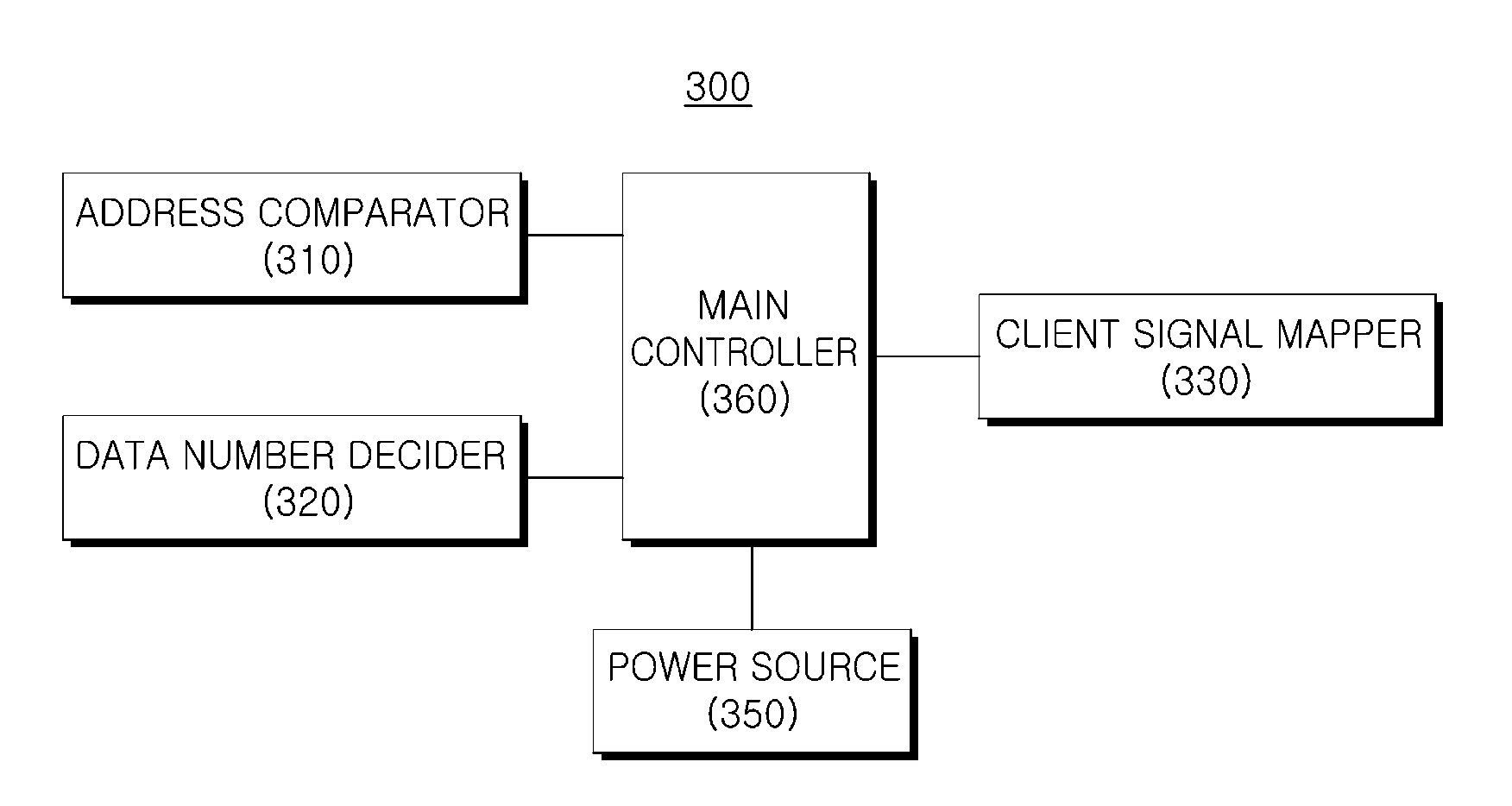
[0089]Referring to FIG. 7, the mapping apparatus 700 includes an elastic store 710, an elastic store write address (WA) generator 720, an elastic store read address (RA) generator 730, an address comparator 740, a Cm / CnD decision processor 750, a 16-byte down-shifter 760, and a JC encoder 770. In this embodiment, the mapping apparatus 700 receives a 256-bit (32-byte) parallel signal.

[0090]The elastic store 710 functions to store received client data and output data at data mapping timing. The elastic store write address generator 720 generates a write address (WA) such that the received client data is stored in the elastic store 710. The elastic store read address generator 730 generates an address of data to be read from the elastic store 710. The address comparator 740 compares a difference between WA and RA, which are r...

second embodiment

[0096]FIG. 9 is a block diagram of an apparatus 900 for mapping an STM-256 signal and all 40-Gbps client signals according to the present invention. The mapping apparatus 900 of FIG. 9 may implement the same function as the mapping apparatus of FIG. 7 by using a variable shifter 910 instead of the 16-byte down-shifter 760. While the 16-byte down-shifter 760 supports only the function of down-shifting the entire 16 bytes, the variable shifter 910 also supports an up- or down-shift on a byte basis. A shifter write enable (s_wEN) signal, a shifter write address (s_wa) signal, and a shifter read address (s_ra) signal, which are input to the variable shifter 910, are provided from the Cm / CnD decision processor 750. When the s_wEN signal is high, s_wa is increased by 32 at every clock. If no shift is generated, s_ra is also increased by 32 at every clock when the s_wEN signal is high. If s_ra is increased by not +32 but +1, a 1-byte up-shift effect may be obtained. If s_ra is increased by...


PUM


Abstract

Disclosed are an apparatus and a method for mapping an SDH signal and other 40-Gbps client signals through a single data path. The mapping apparatus supports both a justification byte mapping scheme and a sigma-delta distribution mapping scheme and implements a single data path. Accordingly, power consumption may be reduced by changing each mapping mode in a hitless manner or minimizing logic capacity according to a mapping mode used in the mapping apparatus.

Description

CROSS-REFERENCE TO RELATED APPLICATIONS[0001]This application claims priority to and the benefit of Korean Patent Application No. 10-2010-0120542 and 10-2011-0025333 filed in the Korean Intellectual Property Office on Nov. 30, 2010, and Mar. 22, 2011, the entire contents of which are incorporated herein by reference.TECHNICAL FIELD[0002]The present invention relates to an apparatus and a method for mapping a client signal. In particular, the present invention relates to an apparatus and a method for mapping a client signal in an Optical Transport Network (OTN) system.BACKGROUND ART[0003]ITU-T G.709 defines one high-rate frame, i.e., an Optical channel Transport Unit-k (OTUk) (k=1, 2, 3, 4), so as to map a variety of client signals to one high-rate frame through a Time Division Multiplexing (TDM) scheme and transmit the mapped signals over an Optical Transport Network (OTN). One OTUk includes an Optical channel Data Unit (ODUk) and parity bytes for error correction of the ODUk. The O...

Claims


Application Information

Patent Timeline
Patent Type & Authority Patents(United States)
IPC IPC(8): H04J3/06H04J3/16
CPCH04J3/167H04J3/0623H04J2203/0089
Inventor SHIN, JONG YOONKIM, JONG HOYOUN, JI WOOK
Owner ELECTRONICS & TELECOMM RES INST
Why Eureka
Try Eureka