Image forming apparatus

a technology of forming apparatus and forming sheet, which is applied in the direction of electrographic process apparatus, thin material processing, instruments, etc., can solve the problems of increasing production costs, degrading both sheet feeding and image quality, and achieving the effect of preventing the adherence of dus

Active Publication Date: 2015-04-07
RICOH KK
View PDF40 Cites 12 Cited by
  • Summary
  • Abstract
  • Description
  • Claims
  • Application Information

AI Technical Summary

Benefits of technology

[0008]In view of the foregoing, illustrative embodiments described herein provide a novel image forming apparatus that reliably discharges a sheet having an image thereon to a stacking unit while preventing the sheet from contacting a sheet roll supported by a sheet roll supporter with an uncomplicated and inexpensive configuration. In addition, the image forming apparatus also prevents adherence of dust and so forth to the sheet roll set to the image forming apparatus.

Problems solved by technology

However, because the sheet roll is substantially exposed to the outside of the image forming apparatus, dust may adhere to the sheet roll, thereby degrading both sheet feeding and image quality.
However, although the sheet roll is securely protected from dust in the above-described example, a configuration of the sheet feed tray is complicated, thereby increasing production costs.

Method used


Image

  • Image forming apparatus
  • Image forming apparatus
  • Image forming apparatus

Examples


Embodiment Construction

[0039]In describing illustrative embodiments illustrated in the drawings, specific terminology is employed for the sake of clarity. However, the disclosure of this patent specification is not intended to be limited to the specific terminology so selected, and it is to be understood that each specific element includes all technical equivalents that operate in a similar manner and achieve a similar result.

[0040]Illustrative embodiments of the present invention are now described below with reference to the accompanying drawings.

[0041]In a later-described comparative example, illustrative embodiment, and exemplary variation, for the sake of simplicity the same reference numerals will be given to identical constituent elements such as parts and materials having the same functions, and redundant descriptions thereof omitted unless otherwise required.

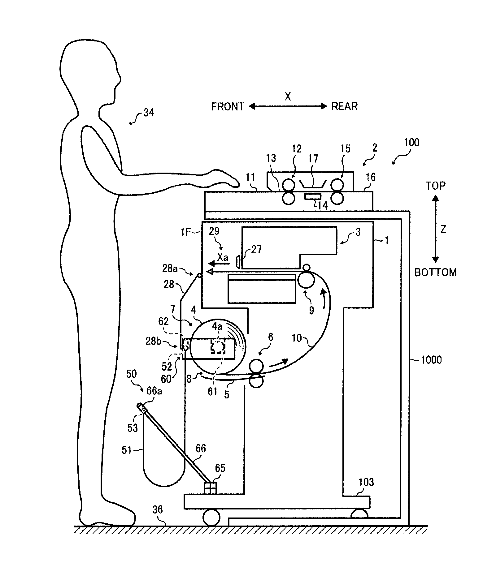
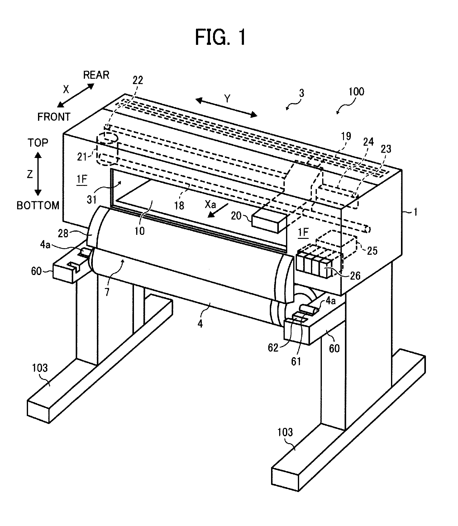
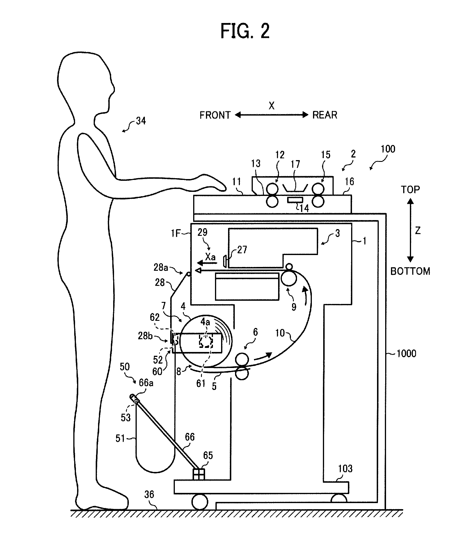
[0042]A configuration and operation of an image forming apparatus 100 according to a first illustrative embodiment are described in detail be...


PUM


Abstract

An image forming apparatus including a sheet roll supporter disposed below a main body of the image forming apparatus to support a sheet roll such that a sheet is fed from the sheet roll, an image forming unit to form an image on the sheet fed from the sheet roll, a sheet discharger disposed downstream from the image forming unit in a direction of conveyance of the sheet to discharge the sheet having the image thereon in a sheet discharging direction, a guide unit to guide the sheet discharged from the sheet discharger to the front of the main body of the image forming apparatus, and a stacking unit on which the sheet passing the guide unit is stacked. Upper and front parts of the sheet roll are covered with the guide unit and the stacking unit across a width direction of the sheet perpendicular to the sheet discharging direction.

Description

CROSS-REFERENCE TO RELATED APPLICATION[0001]The present patent application is based on and claims priority pursuant to 35 U.S.C. §119 from Japanese Patent Applications No. 2011-168443, filed on Aug. 1, 2011, No. 2011-180771, filed on Aug. 22, 2011, and No. 2012-104851, filed on May 1, 2012, all in the Japan Patent Office, each of which is incorporated by reference herein in its entirety.BACKGROUND OF THE INVENTION[0002]1. Field of the Invention[0003]Illustrative embodiments described in this patent specification generally relate to an image forming apparatus employing an inkjet method or an electrophotographic method, such as a copier, a printer, a plotter, a facsimile machine, and a multifunction device having two or more of copying, printing, plotting, and facsimile capabilities, and more particularly to an image forming apparatus including a stacking unit on which a sheet fed from a sheet roll set to the image forming apparatus is stacked after the sheet having an image thereon i...

Claims


Application Information

Patent Timeline
Patent Type & Authority Patents(United States)
IPC IPC(8): B65H31/22B41J15/04B41J11/70B41J13/10
CPCB41J11/70B41J13/106B41J15/046
Inventor SAIGA, SOICHI
Owner RICOH KK
Why Eureka
Try Eureka