Configurable shielded enclosure with signal transfer element

a shielded enclosure and signal transfer technology, applied in the field of shielded enclosures, can solve the problems of unwarranted invasion of privacy, unfavorable monitoring of the location of the device, and the inability to monitor continuously, so as to achieve the effect of greater selection control

Inactive Publication Date: 2015-04-07
REIBLE JAMES PATRICK
View PDF30 Cites 13 Cited by
  • Summary
  • Abstract
  • Description
  • Claims
  • Application Information

AI Technical Summary

Benefits of technology

[0011]In an alternative embodiment, one or more narrow-band and / or filtered signal-transfer elements are employed to allow greater control of selecting which signals can reach the contained device.

Problems solved by technology

However, owner's of these devices may not wish to have the location of the device to be continuously available for monitoring.
Having the location information being continuously available may result in unwarranted invasions of the privacy of the owner of the device as someone else may able to use the location information to determine the location of the device and, thus, the location of person owning the device.
Moreover, information that is stored on a portable electronic device may also be accessed by unscrupulous entities when the device is actively transmitted and receiving.

Method used


Image

  • Configurable shielded enclosure with signal transfer element
  • Configurable shielded enclosure with signal transfer element
  • Configurable shielded enclosure with signal transfer element

Examples


first embodiment

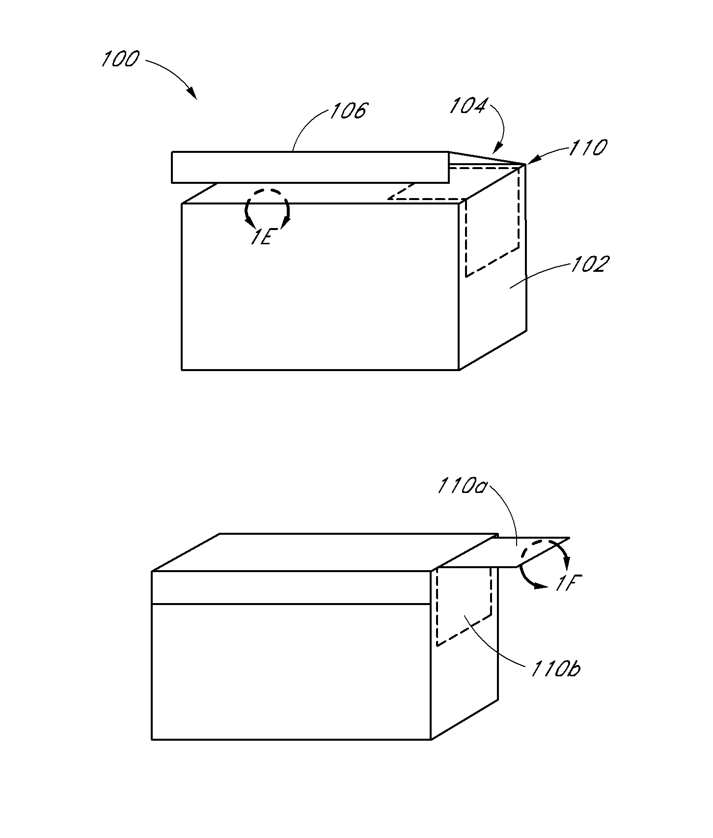
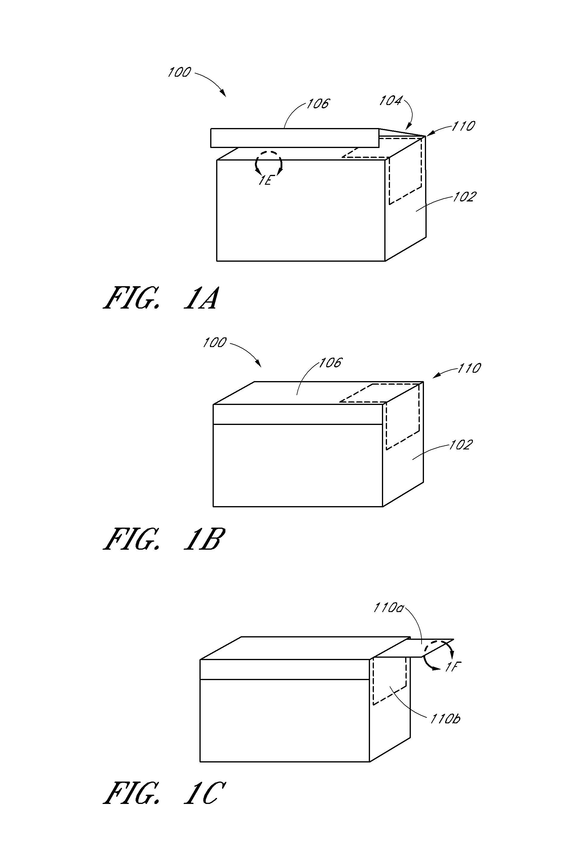
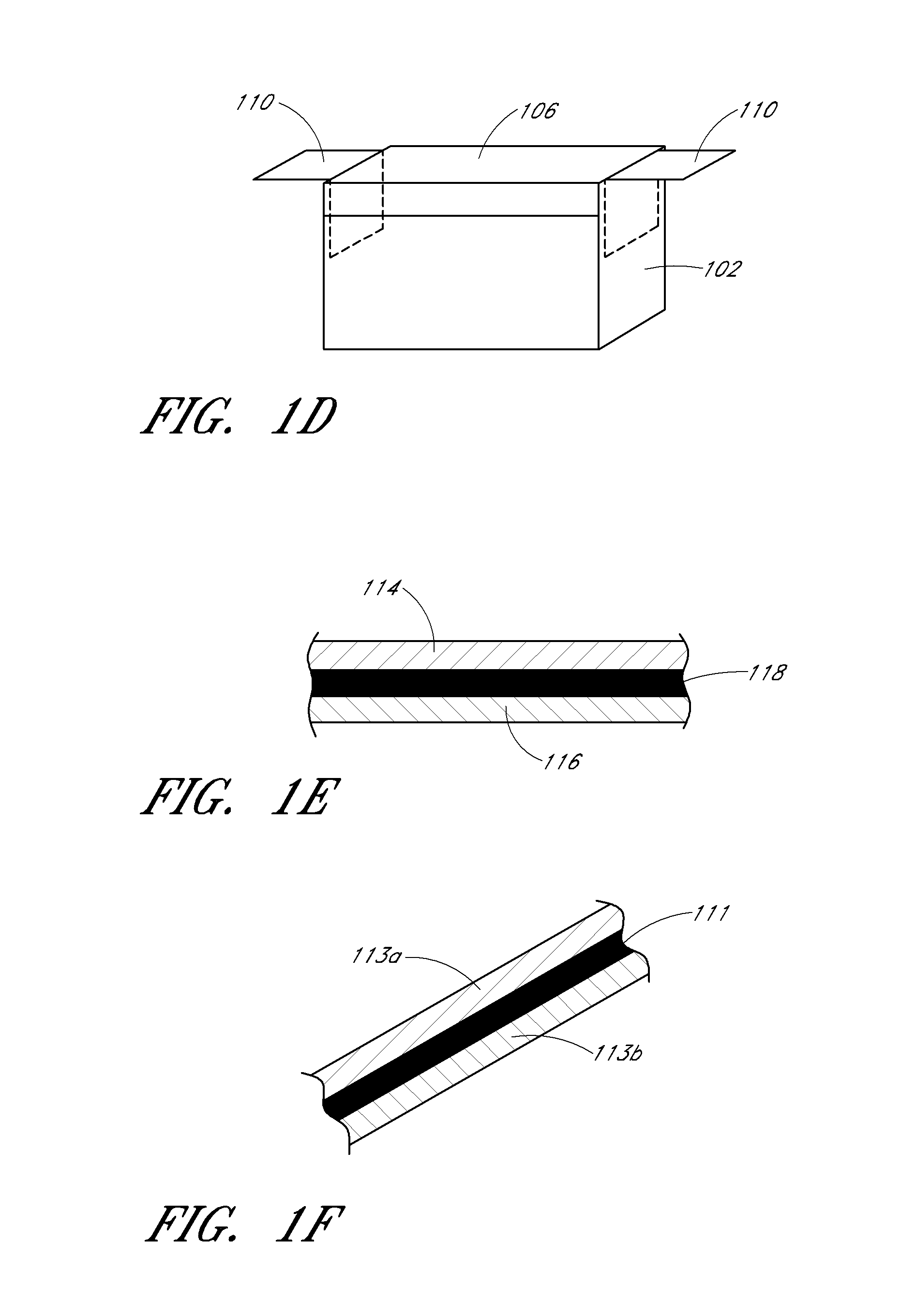
[0027]Reference will now be made to the drawings wherein like numerals refer to like parts throughout. Referring initially to FIGS. 1A-1D, a configurable shielded enclosure 100 for use with a portable electronic device is shown. As shown, the enclosure 100 includes a housing 102 that defines an interior space 104 that is sized so as to receive a portable electronic device such as a cellular phone, smart phone etc. The shape and configuration of the housing 102 and the interior space 104 can vary without departing from the spirit or scope of the present invention.

[0028]As is also shown in FIGS. 1A-1D, the enclosure 100 includes a access port 106 or door 106 that is movable between an open configuration where the portable electronic device can be positioned within or removed from the interior space 104 and a closed configuration where the portable electronic device is secured within the housing 102.

[0029]As is also shown in FIGS. 1A-1D, the enclosure 100 also includes a signal transfe...

embodiment 600

[0048]FIG. 6A-6C illustrate another embodiment 600 of an enclosure that has a housing 102 that defines an interior space 104 and an access port 106 that is formed of either a fully or partially removable cover 606. The enclosure 600 includes a signal transfer element 610 that is partly positioned on the outside of the housing 102 and has a conductive surface adjacent and edge of the housing 102.

[0049]The cover 606 also includes a shield layer 118 that is exposed and can contact the signal transfer element 610 and also the shield layer 118 in the other walls of the housing 102. When the cover 610 is positioned on the housing 102 in the manner shown in FIG. 6B, the signal transfer element 610 is at the same electrical potential as the shield layer 118 via the contact with the portion of the shield layer 118 and thus part of the shielding of the interior space 104 of the housing 102.

[0050]When the cover 606 is fully removed from the housing 102 in the manner shown in FIG. 6A, communica...


PUM


Abstract

An enclosure that has an interior space sized to receive a portable electronic device. The enclosure has a shielding layer that can shield and prevent communications between the interior space and the outside world in a first configuration. In a second configuration, communication is allowed. A signal transfer element is attached to the enclosure housing that can be moved between an isolation configuration and a communication configuration.

Description

CROSS-REFERENCE TO RELATED APPLICATIONS[0001]This application claims the benefit of U.S. provisional application No. 61 / 590,716 entitled CONFIGURABLE SHIELDED ENCLOSURE WITH SIGNAL TRANSFER ELEMENT filed Jan. 25, 2012.BACKGROUND OF THE INVENTION[0002]1. Field of the Invention[0003]The present invention relates to a shielded enclosure that can contain a transmitting and receiving device and, in particular, concerns a shielded enclosure that can selectively allow communications to and from a transmitting and / or receiving electronic device such as a cellular telephone, smart phone etc.[0004]2. Description of the Related Art[0005]Cellular telephones, smart phones, tablets and other similar portable electronic devices have become ubiquitous in recent years. The functionality of these portable devices have also increased very dramatically in recent years. For example, these portable electronic devices can incorporate GPS functionality where the device is receiving information that indicat...

Claims


Application Information

Patent Timeline
Patent Type & Authority Patents(United States)
IPC IPC(8): H04B17/00H05K9/00A47B81/06G06K19/073
CPCA47B81/06G06K19/07327H05K9/0045H05K9/0018G06K19/07318H05K9/0009H05K9/0049H05K9/006H05K9/0084
Inventor REIBLE, JAMES PATRICK
Owner REIBLE JAMES PATRICK
Why Eureka
Try Eureka