
Hand-held rivet nut (rivet bolt) tool with quick-change mandrel

a technology of rivet nut and mandrel, which is applied in the direction of metal-working hand tools, metal-working apparatuses, metal-working apparatus, etc., can solve the problems of increasing manufacturing time and cost, reducing production efficiency, and complicated manufacturing process of such holding structure, so as to reduce manufacturing time and cost.

Active Publication Date: 2015-04-14
KARAT INDAL CORP
View PDF11 Cites 6 Cited by
  • Summary
  • Abstract
  • Description
  • Claims
  • Application Information

AI Technical Summary

Benefits of technology

The present invention provides a hand-held rivet nut (rivet bolt) tool with a quick-change mandrel that reduces manufacturing time and costs. The tool includes a body, a sleeve, a positioning ring, and a mandrel. The mandrel can be easily disengaged from a jammed rivet nut or rivet bolt without destroying the work piece or tool. The tool also includes a limit piece and a limit piece retainer for easy disengagement of the mandrel. The manufacturing process of the holding structure between the mandrel and sleeve is simplified, increasing production efficiency and reducing manufacturing time and costs.

Problems solved by technology

However, the manufacturing process of such holding structure is complicated because it comprises steps of drilling and tapping the threaded hole 71, putting the ball 72 and spring 73 into the threaded hole 71 and then screwing the bolt 74 into the threaded hole 71, which decreases production efficiency and increases manufacturing time and costs.
Furthermore, when the rivet nut 90 is jammed on the mandrel 80, the work piece or rivet nut tool must be destroyed in order to take out the jammed rivet nut 90, thus causing huge inconvenience.

Method used


Image

  • Hand-held rivet nut (rivet bolt) tool with quick-change mandrel
  • Hand-held rivet nut (rivet bolt) tool with quick-change mandrel
  • Hand-held rivet nut (rivet bolt) tool with quick-change mandrel

Examples


Embodiment Construction

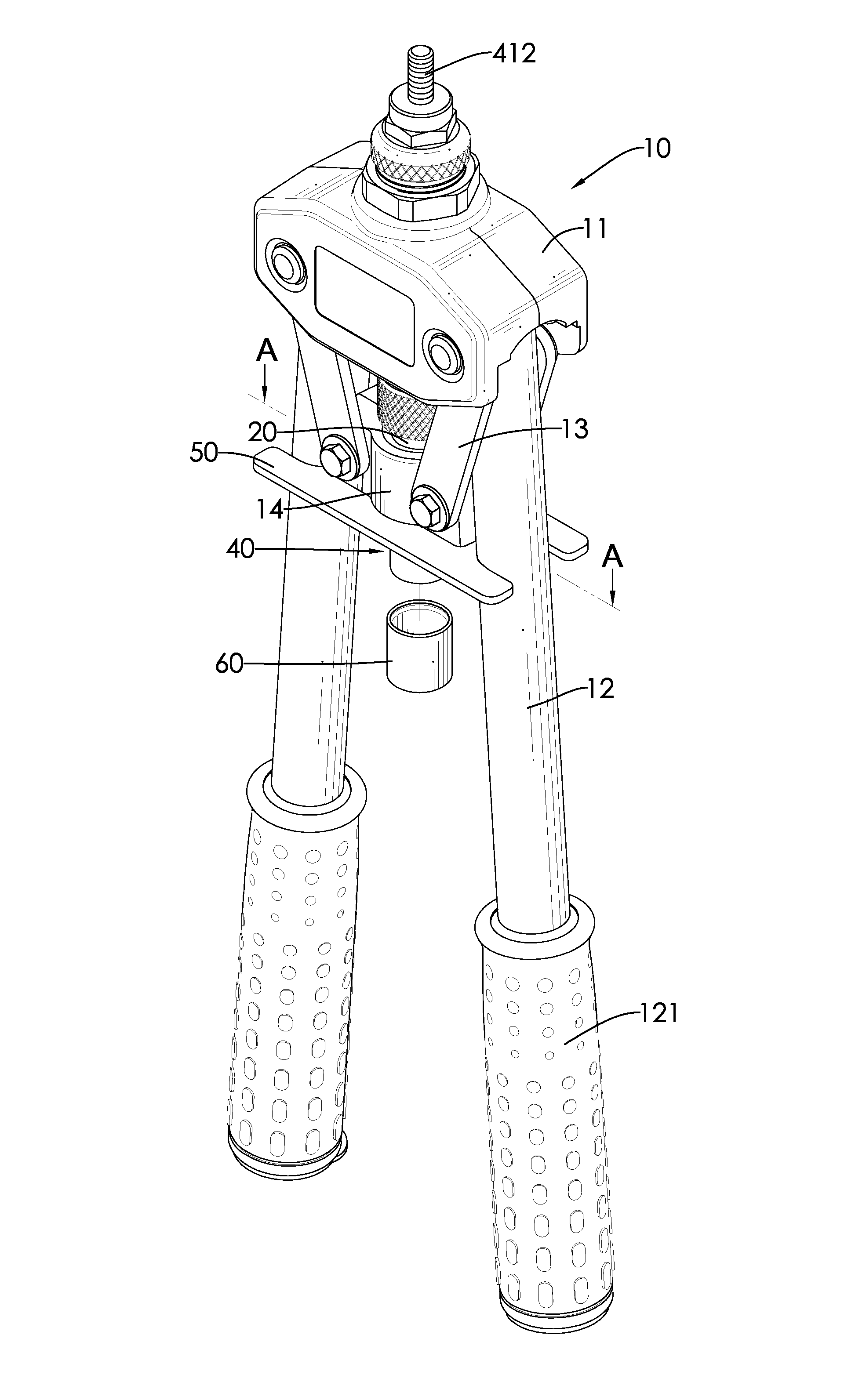
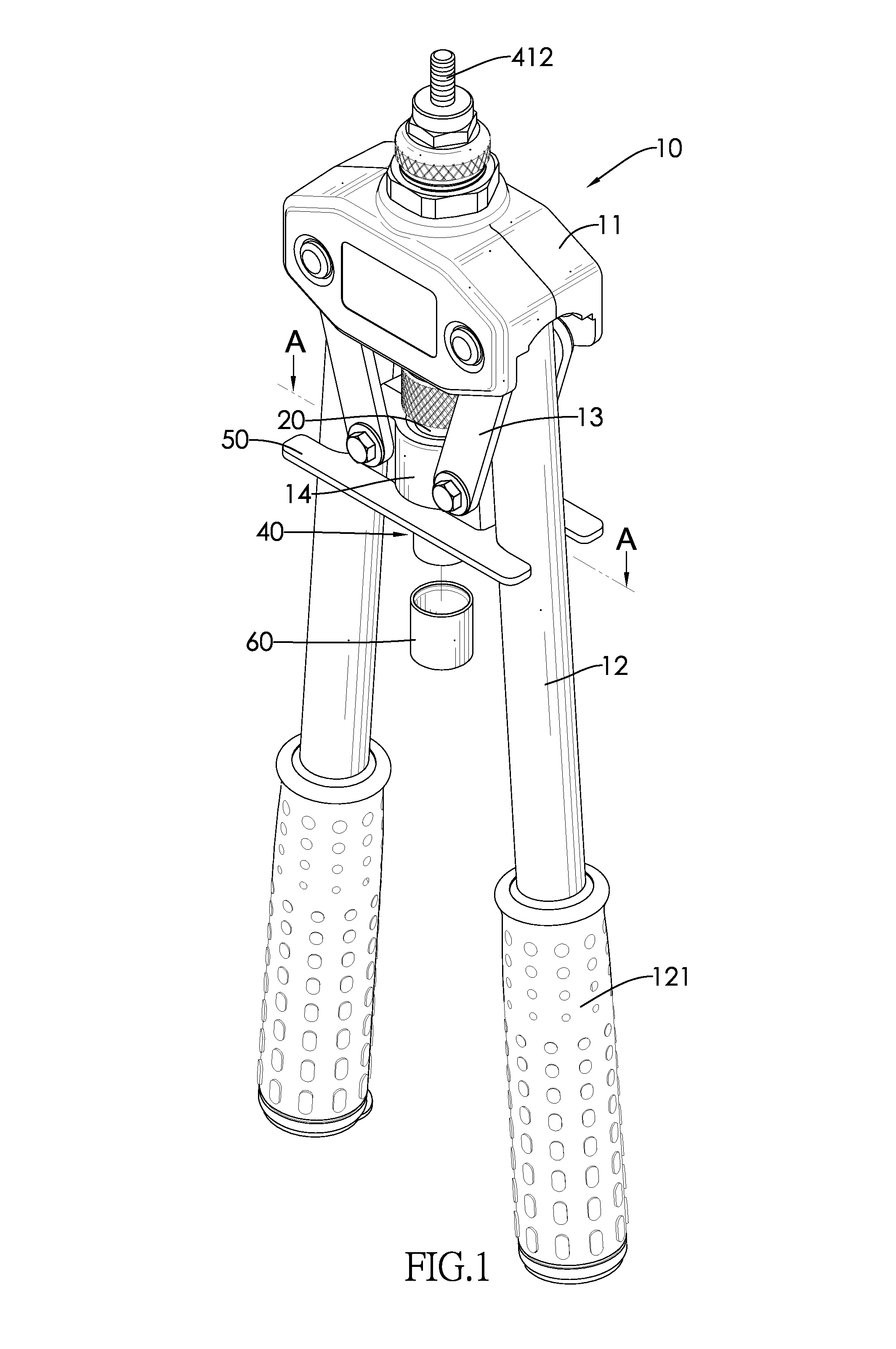
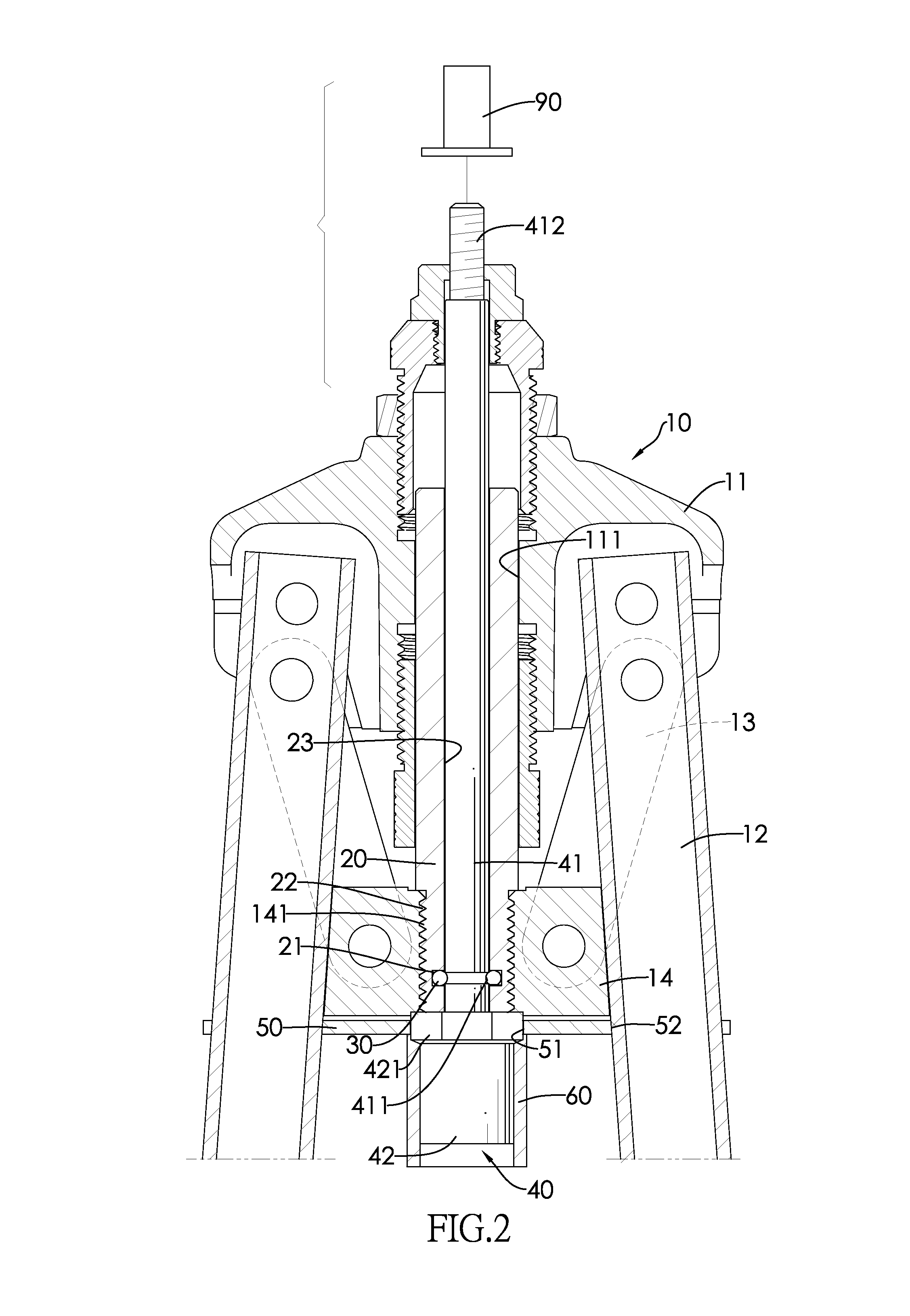
[0020]With reference to FIGS. 1, 2 and FIGS. 5, 6, a hand-held rivet nut (rivet bolt) tool in accordance with the present invention comprises a body 10, a sleeve 20, a positioning ring 30, a mandrel 40, 40A and a limit piece 50.

[0021]The body 10 includes a base 11, a pair of handles 12, a pair of links 13 and a driven member 14. The base 11 has a bottom surface, a center, two sides and a bore 111. The bore 111 extends through the center of the base 11. The handles 12 are respectively pivotally connected to the two sides of the base 11. Each handle 12 has a grip 121 at a lower portion thereof. The driven member 14 is disposed below the base 11 between the handles 12 and has a bottom surface, a center, two sides and a threaded hole 141. The two sides of the driven member 14 are respectively pivotally connected to the handles 12 by the links 13. The threaded hole 141 extends through the center of the driven member 14 and aligns with the bore 111 of the base 11.

[0022]The sleeve 20 is ax...


PUM

PropertyMeasurementUnit
sizesaaaaaaaaaa
thread sizesaaaaaaaaaa
areaaaaaaaaaaa

Abstract

A hand-held rivet nut (rivet bolt) tool has a body, a sleeve, a positioning ring and a mandrel. The body includes a base and a pair of handles. The handles are respectively pivotally connected to two sides of the base. The sleeve is axially movably mounted through the base and includes an annular mounting groove. The positioning ring is seated in the annular mounting groove of the sleeve and includes an inner portion. The mandrel is rotatably mounted through the sleeve and includes an annular positioning groove allowing the inner portion of the positioning ring to engage therewith. The manufacturing process of the holding structure between the mandrel and sleeve is simplified because it only has steps of forming the annular mounting groove and then seating the positioning ring in the annular mounting groove, which increases production efficiency and reduces manufacturing time and costs.

Description

BACKGROUND OF THE INVENTION[0001]1. Field of the Invention[0002]The present invention relates to a hand-held rivet nut (rivet bolt) tool, and more particularly to a hand-held rivet nut (rivet bolt) tool having a quick-change mandrel that reduces manufacturing time and costs, also offering a solution to solve the headache problem of rivet nut (rivet bolt) jammed with the mandrel.[0003]2. Description of the Related Art[0004]A hand-held rivet nut (rivet bolt) tool is adapted to set rivet nuts (rivet bolts) in a work piece. With reference to FIGS. 8 and 9, a conventional hand-held rivet nut tool disclosed in U.S. Pat. No. 5,729,880 comprises a body 60, an operating handle 61, a sleeve 70 and a mandrel 80. The operating handle 61 is pivotally connected to the body 60. The sleeve 70 is movably mounted through the body 60, is actuated by the operating handle 61 and has a threaded hole 71 extending radially therethrough for receiving a ball 72, a spring 73 and a bolt 74. The spring 73 urges...

Claims


Application Information

Patent Timeline
Patent Type & Authority Patents(United States)
IPC IPC(8): B23P11/00B21D31/00B21D9/05B21J15/38B25B27/00
CPCB21J15/386B25B27/0007Y10T29/5373Y10T29/53757Y10T29/5377
Inventor KO, PHILEY
Owner KARAT INDAL CORP
Learn More