Fluid mixer using countercurrent injection

a technology of countercurrent injection and mixer, which is applied in the field of blending systems, can solve the problems of syrup slug being presented to the diffuser, lack of blending that occurs in the mixing chamber upstream of the diffuser, and poor beverage blending

Active Publication Date: 2015-04-14
TECHNIBLEND LLC
View PDF53 Cites 274 Cited by
  • Summary
  • Abstract
  • Description
  • Claims
  • Application Information

AI Technical Summary

Benefits of technology

[0006]In addition, conventional blending systems have utilized pump control to regulate the flow of syrup and liquid along respective supply conduits to the mixing chamber. Nipple valves are usually provided at the dispensing ends of each supply conduit. When the pumps are shut off at the end of a dispensing cycle, forced flow of syrup and liquid along the supply: conduits ceases. However, because of the density of the syrup, it is not uncommon for some syrup to leak out of the nipple valve into the mixing chamber. If the liquid medium is also leaked into the mixing chamber, the leakage of syrup would be less problematic. However, the less dense liquid medium typically does not leak past the nipple valve at the end of the liquid supply conduit. The introduction of residual of syrup to the mixing chamber can disturb the ratio of syrup and liquid in the mixing chamber when the dispenser is cycled back on.
[0041]While additional blending or mixing of the cone-shaped stream may be needed, the countercurrent injection of the beverage syrup into a stream of liquid is believed to provide numerous advantages over conventional blending setups. For example, the present invention provides a substantially uniform or consistent distribution of the fluids. That is, there is not a significant separation of the beverage syrup from the liquid in the blended stream. The check valves provide relatively precise metering of the beverage syrup and the liquid, which is believed to reduce concentration spikes. Further, the use of check valves provides better control during periods of non-mixing. In conventional setups, as noted above, it is common for the heavier fluids to continue to fall into the mixing volume when the mixing process is stopped. This can result in a concentration slug that must be accounted for at resumption of the blending process, such as large averaging tanks, which the present invention does not require.

Problems solved by technology

One of the drawbacks of conventional beverage blending systems is the lack of blending that occurs within the mixing chamber upstream of the diffuser.
While there may be some dispersion of the beverage syrup into the stream of liquid, or vice-versa, for the most part, these separate components remain relatively separate from one another until presented to the diffuser, which can result in a syrup slug being presented to the diffuser.
While the diffuser will expand the slug and provide a certain amount of blending, it is possible for the slug to overwhelm the diffuser and result in a poorly blended beverage.
Poor mixing of syrup and liquid can result in an incorrect ratio of syrup to liquid medium.
However, because of the density of the syrup, it is not uncommon for some syrup to leak out of the nipple valve into the mixing chamber.
The introduction of residual of syrup to the mixing chamber can disturb the ratio of syrup and liquid in the mixing chamber when the dispenser is cycled back on.
The above-described lack of precision in controlling the amounts of syrup and liquid medium can be exaggerated when additional ingredients are added, such as flavoring or the like.

Method used


Image

  • Fluid mixer using countercurrent injection
  • Fluid mixer using countercurrent injection
  • Fluid mixer using countercurrent injection

Examples


Embodiment Construction

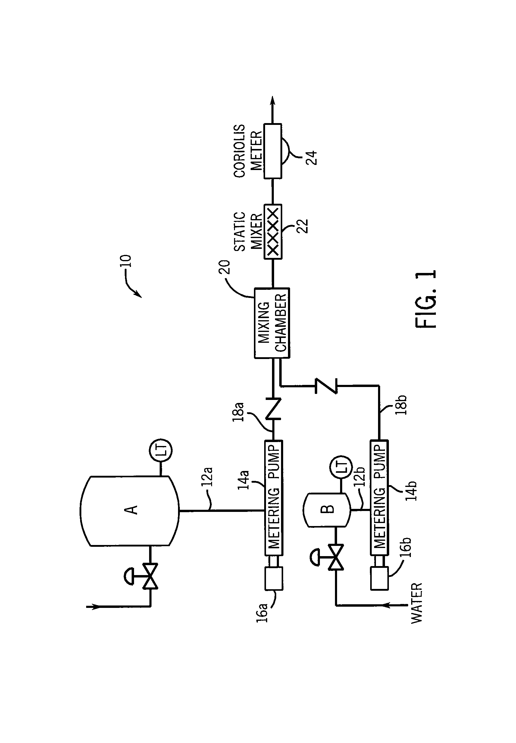
[0028]FIG. 1 provides a general illustration of a blending system 10 according to one embodiment of the present invention. As shown in FIG. 1, a first liquid component is supplied from a source A, which may be a tank or reservoir (or alternatively may simply be a pipe that supplies the liquid component), and a second liquid component is supplied from a source B, which again may be a tank or reservoir (or alternatively may simply be a pipe that supplies the liquid component). The two liquid components are destined to be mixed or blended together to form a final, blended product.

[0029]From source A, the first liquid component is supplied through a line 12a to a metering pump 14a, which is driven by a motor 16a. Similarly, the second liquid component is supplied through a line 12b to a metering pump 14b, which is driven by a motor 16b. The metering pumps 14a, 14b function to accurately dispense desired quantities of the first and second liquid components according to a predetermined ra...


PUM

PropertyMeasurementUnit
densityaaaaaaaaaa
volumeaaaaaaaaaa
mixing volumeaaaaaaaaaa

Abstract

A method and apparatus for mixing fluids, such as beverage syrup and water, uses countercurrent injection to improve blending of the fluids. A mixing chamber has a first inlet through which a first fluid is fed to the mixing chamber, and a second inlet through which a countercurrent injection nozzle extends and is operative to inject a second fluid into a stream of the first fluid. The countercurrent injection nozzle is equipped with a check valve to control the flow of fluid into the mixing chamber. The mixing chamber may include additional inlets that may be fitted with countercurrent injection nozzles to permit the countercurrent injection of other fluid, such as flavorings, into the stream of the first fluid.

Description

CROSS-REFERENCE TO RELATED APPLICATION[0001]This application claims the benefit of U.S. Ser. No. 61 / 164,688 filed Mar. 30, 2009, the disclosure of which is incorporated herein.FIELD OF INVENTION[0002]The present invention is directed to blending systems and, more particularly, to a method and system of blending fluids using countercurrent injection.BACKGROUND AND SUMMARY OF THE INVENTION[0003]Liquid blending systems, such as those used to mix beverage syrup and water, typically introduce a stream of beverage syrup and a stream of liquid such as water to a mixing chamber. In the mixing chamber, the syrup and the liquid mix with one another to provide a partially blended beverage. The partially blended beverage typically then flows to a static diffuser, which functions to fully blend the beverage. One type of diffuser includes a series of plates in a stacked arrangement. The partially blended beverage is radially expanded by the surface of the plates, and the spaced arrangement of the...

Claims


Application Information

Patent Timeline
Patent Type & Authority Patents(United States)
IPC IPC(8): B01F15/02B01F5/10
CPCB01F5/108B01F23/453B01F2025/918B01F25/31323B01F25/313B01F2101/14B01F25/54
Inventor KEMP, DAVID M.
Owner TECHNIBLEND LLC
Why Eureka
Try Eureka