Muscle and/or joint exercise apparatus

a joint exercise and muscle technology, applied in the field of muscle and/or joint exercise apparatus, can solve the problems of hardly being parameterized, reducing the choice of movement of the limb, and heavy apparatuses

Active Publication Date: 2015-04-14
CHAMPSAUR MARC
View PDF11 Cites 3 Cited by
  • Summary
  • Abstract
  • Description
  • Claims
  • Application Information

AI Technical Summary

Benefits of technology

[0049]This apparatus has the advantage of being lightweight and compact, transportable or portable, mainly comprising the hollow body, the motor-driven means, and the mobile member. The space required for such an apparatus is substantially the space required for the body, when the arm is retracted at least partially inside the body; the motor-driven means being advantageously fastened to the bottom of the body, inside or outside the body. Thus, this apparatus is easy to transport by hand or in a car, e.g. enabling a therapist or a sports trainer to move around with one or several apparatuses in accordance with the invention and visit his / her patients or clients to make them do exercises on these apparatuses.
[0158]Thus, the control method and the associated apparatus allow to control the motor-driven means and the secondary motor-driven means in order to regulate the movement of the mobile member around a predefined path, allowing for the body part of the user (generally an upper or lower limb) to be worked in space, with the advantage of working specific muscle chains, according to a selected program or exercise protocol.

Problems solved by technology

Such apparatuses are generally heavy and cumbersome, can hardly be parameterized, offer a reduced choice of movement for the limb, are difficult to self-install and difficult to transport.
Such discontinuities are inevitable, not adjustable, and the stronger the heavier the weight to lift or retain.
And yet, such sudden variations in effort will generate large stresses at:tendons, possibly leading to tendinitis issues in case of fatigue; andjoints, limiting the use of such apparatuses for people with joint problems, but still wishing to train the muscles of the relevant limb.
Furthermore, such sudden variations in effort put heavy strain on the cardiac system, because the heart must respond to this sudden muscle effort.
Thus, people having cardiac weaknesses, as for instance people bearing pacemakers, cannot use such apparatuses, or only in a very limited way.
Therefore, this respiration will not allow for correct supply of oxygen, and the muscle will exercise in anaerobia, in other words with a deficit of oxygenation.
Such straining of all fibers may be harmful for people with muscle contusions on certain fibers, so that training of this muscle cannot be carried out with such an exercise apparatus.
Also, these apparatuses are not adapted for persons having a weakened and / or painful tendon and who can exercise their limb only in a limited movement range of the relevant limb.
These constant and repeated efforts of traction and resistance will indeed apply efforts on the limb being exercised, but will also strain the patient's posture holding muscles.
During the exercise, the patient's compensation will not be identical all the time, and his / her posture may deviate, with the risk of generating long term muscle issues.
Moreover, the known muscle training apparatuses are generally not multipurpose or multifunctional in that such apparatuses have hinges specifically dedicated to exercising certain muscles or certain limbs or parts of a limb, such as an arm, a shoulder, an elbow, a wrist, a thigh, an ankle, etc.
Such apparatuses and systems have the disadvantage of being cumbersome and difficult to transport, not to mention that they are limited to exercising the lower limbs, or even only to exercising the knee, by using such a rotationally mobile member.
However, such apparatuses cannot simultaneously perform bidirectional or multidirectional movements or efforts in that they do not allow for bidirectional or multidirectional movements or efforts to be carried out simultaneously.
However, such an apparatus turns out to be expensive and not well suited for certain types of movement, namely due to the inherent inertia of a displacement controlled by a hydraulic or pneumatic unit.
However, such an apparatus is particularly complex and expensive, and it only allows to exercise in one predefined plane specified by the apparatus.
Such an apparatus turns out to be cumbersome, difficult to transport, and not suitable for certain types of movement due to the limitation of the movement to a simple rotation of the crank.
Thus, this apparatus is not well suited for articular reeducation which requires much greater possibilities of amplitude.
Moreover, this telescopic arm is limited in terms of radial efforts due to the mechanical design thereof.
Indeed, this telescopic arm is not well suited for taking over too forceful radial efforts, and thus limits the exercises to very weak radial efforts.
This apparatus is thus not well suited for muscle strengthening exercises which require great efforts.
The barycenter of this apparatus largely varies during operation, thus requiring compensating mechanisms which are particularly expensive, complex and cumbersome, i.e. mechanisms for regulating the motors and the tow bar brake.
Furthermore, the apparatus described in US 2007 / 0299371 A1 is a solution with four degrees of mobility of which at least three are motorized which is particularly expensive and cumbersome, especially with a work table, and thus limited to reeducation centers, like clinics or hospitals.
With such an apparatus, the exercise is performed in a plane which cannot be parameterized and along a fixed path within the same series of repetitions of the exercise, thus limiting the use thereof to a very limited number of exercises.

Method used


Image

  • Muscle and/or joint exercise apparatus
  • Muscle and/or joint exercise apparatus
  • Muscle and/or joint exercise apparatus

Examples


first embodiment

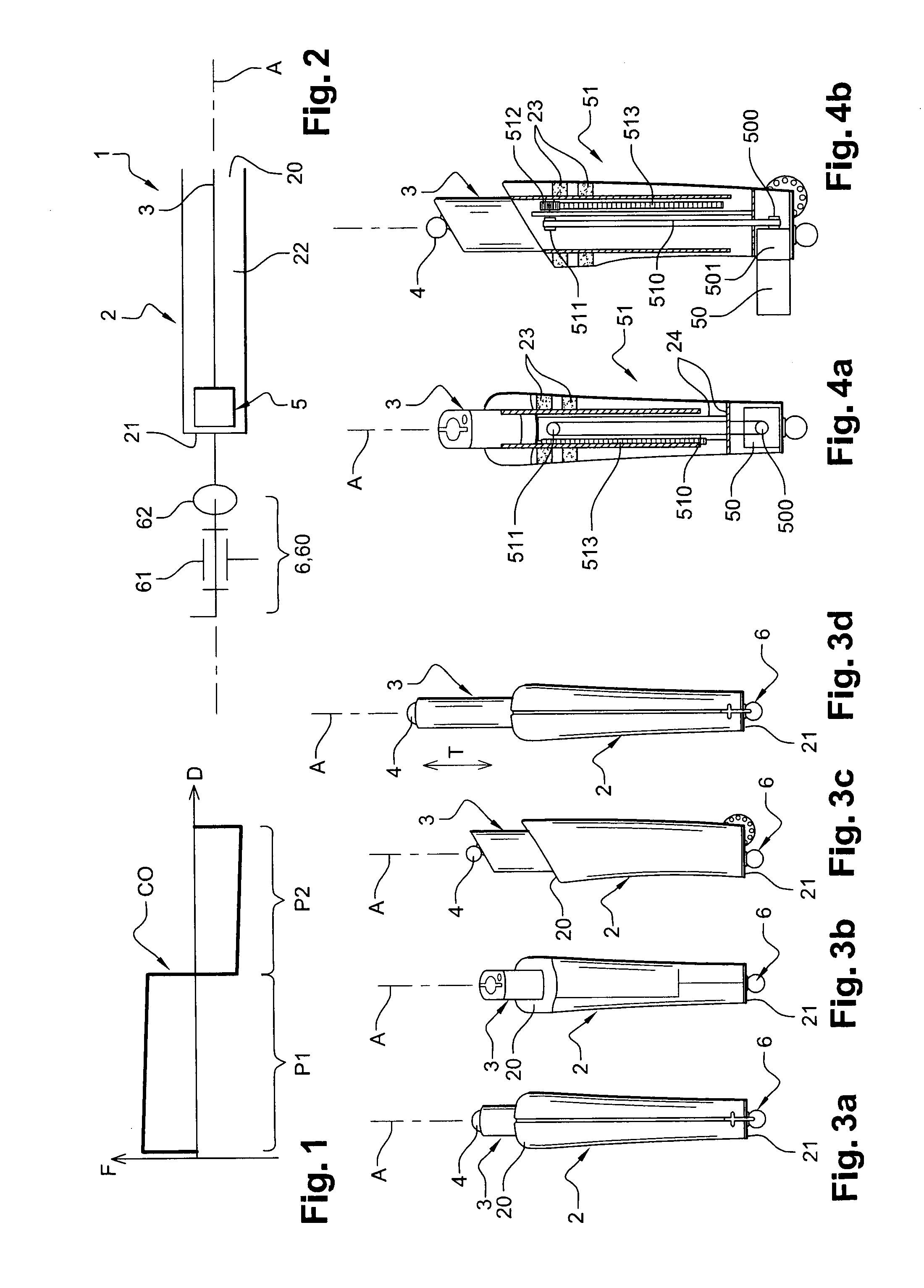
[0281]In the first embodiment illustrated in FIGS. 4a and 4b, the converting means 51 comprise:[0282]a belt 510 rotatingly connected to the rotary motor shaft 500 of the motor 50 on the one hand, and to a pulley 511 fastened to a base 24 integral with the body 2 on the other hand, said base 24 partially extending over the length of the body 2 inside the arm 3 and said belt 510 going through said base 24;[0283]a toothed wheel 512 rotationally integral with the pulley 511 and fastened to the base 24; and[0284]a rack 513 meshing with the toothed wheel 512 and fastened to the arm 3.

[0285]Thus, the rotation of the motor shaft 500 rotatingly drives the pulley 512 via the belt 510, and said pulley 511 rotatingly drives the toothed wheel 512 which by turning translationally displaces the arm 3 via the rack 513. In this embodiment, the motor shaft 500 extends along an axis perpendicular to the main axis A. As illustrated, the motor 50 may protrude from the body 2 via a corresponding opening ...

second embodiment

[0286]In the second embodiment illustrated in FIG. 5, the converting means 51 comprise:[0287]a threaded shaft 514 (e.g. of the ball screw type) rotatingly driven by the motor 50, thereby being the output shaft of said motor 50 and going through the second end 32 of the arm 3 via a bearing 515; and[0288]a nut part 516 fastened to the arm 3 and equipped with a threaded orifice cooperating with the threaded shaft 514.

[0289]Thus, the threaded shaft 514 and the nut part 516 together form a screw / nut system for transforming a rotational movement into a translatory movement: the rotation of the threaded shaft 514 translationally drives the nut part 516 which translationally drives the arm 3. In this embodiment, the threaded shaft 514 extends along the main axis A.

third embodiment

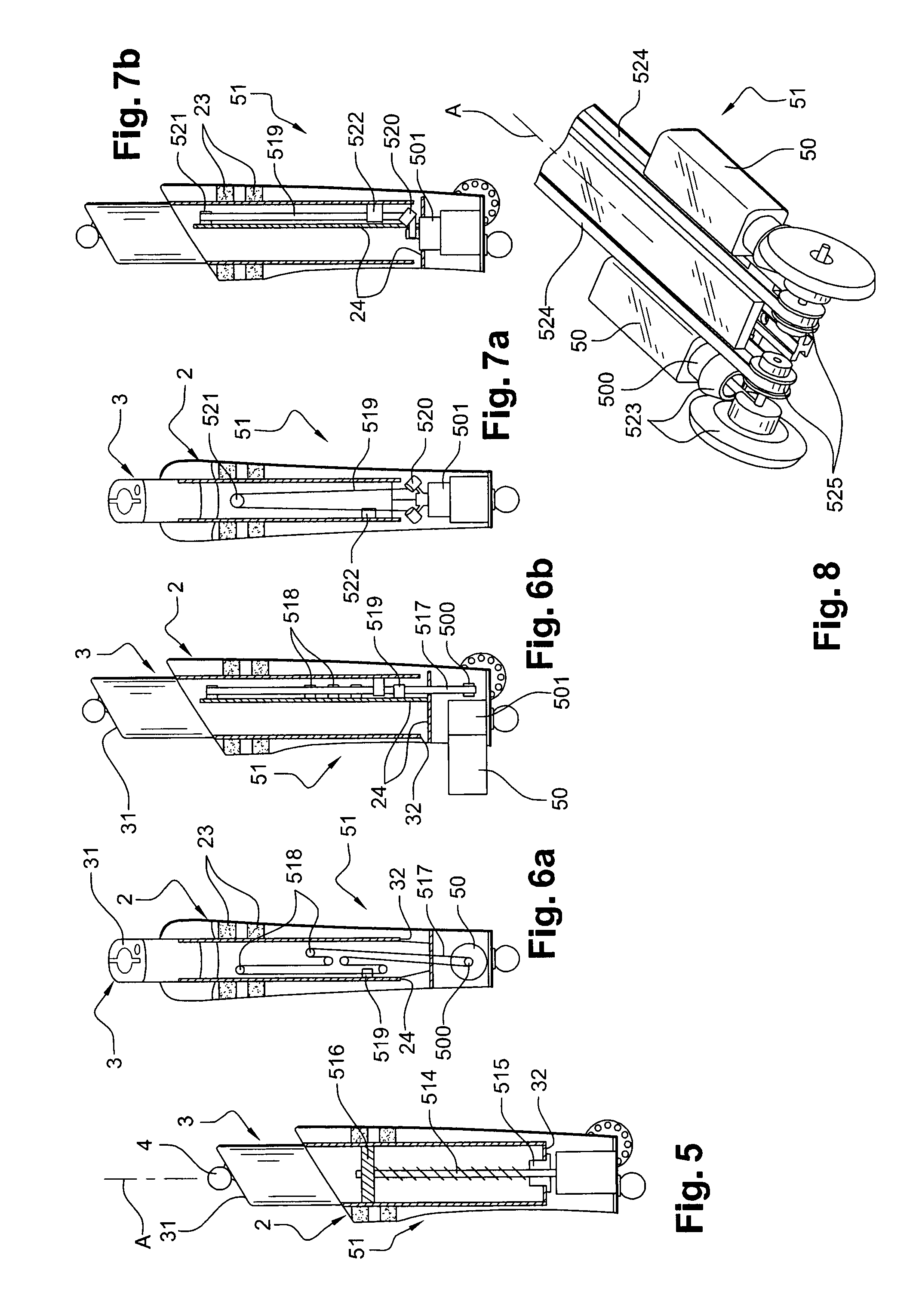
[0290]In the third embodiment illustrated in FIGS. 6a and 6b, the converting means 51 comprise:[0291]a belt 517 rotationally connected to the motor shaft 500 extending along an axis perpendicular to the main axis A;[0292]rollers 518 extending along respective axes perpendicular to the main axis A and guiding the displacement of the belt 517 so that said belt has a long planar portion, between two rollers, which is parallel to the main axis A along the arm 3, there being a total of five of said rollers 518 here which are fastened to a base 24 integral with the body 2 and partially extend over the length of the body 2 inside the arm 3;[0293]a connecting piece 519 integral both with the arm 3 and the long planar portion of the belt 517.

[0294]Thus, the rotation of the motor shaft 500 rotatingly drives the belt 517 around the rollers 518, so that the connecting piece 519 is translationally driven between the two rollers 518 delimiting the long planar portion of said belt 517, thereby tra...


PUM


Abstract

An apparatus of muscle and / or joint exercise adapted to reeducation and / or physical conditioning of a body part of a user, including a hollow body;a mobile member translatable inside the body; a motor-driven means arranged on the bottom of the body and adapted for driving and decelerating in displacement the mobile member in both translatory directions; a cooperating means between the body and a frame, this cooperating means being arranged on the bottom of the body and including: at least one hinge of the body on the frame, the hinge providing at least at least one degree of rotational freedom for the body around an axis of rotation; and a removable means for installing and removing the body, the removable means being designed for removably installing the body on a base slidingly mounted in the frame.

Description

TECHNICAL FIELD[0001]This invention relates to muscle and / or joint exercise apparatus, a muscle and / or joint exercise device comprising such an exercise apparatus, and a method for using the exercise apparatus; such an apparatus being adapted for physical reeducation and / or training of a body part of a user, such as an upper limb (arm) and / or a lower limb (leg), or part of an upper limb part (forearm, wrist, elbow) and / or lower limb (ankle, thigh, knee), or another body part, such as for instance the hip or pelvis.[0002]More particularly, it relates to a muscle and joint exercise apparatus, which may advantageously be used in a hospital, a physiotherapy practice, a sports club, a fitness club, or at the user's home, wherein a user is any person likely to make use of such an exercise apparatus.BACKGROUND[0003]In a known manner, the reeducation of a limb, be it an arm or a leg, subsequently to illness or an accident, mainly comprises the following steps:[0004]a first articular mobiliz...

Claims


Application Information

Patent Timeline
Patent Type & Authority Patents(United States)
IPC IPC(8): A61H1/00A61H1/02A63B24/00A63B21/005A63B71/06
CPCA63B21/0058A63B24/0006A63B24/0075A63B71/0622A63B2024/0012A63B2071/0625A63B2071/0655A63B2220/10A63B2220/20A63B2220/24A63B2220/30A63B2220/40A63B2220/51A63B2220/54A63B2220/62A63B2220/72A63B2220/74A63B2220/75A63B2225/20A63B2225/50A63B21/00181A63B21/002
Inventor CHAMPSAUR, MARC
Owner CHAMPSAUR MARC
Why Eureka
Try Eureka