Positioning device for an optical triangulation sensor

a technology of positioning device and triangulation sensor, which is applied in the field of measurement equipment, can solve the problems of limiting the accuracy and repeatability of measurements, and achieve the effect of accurately located and increasing the hole size rang

Active Publication Date: 2015-04-21
THIRD DIMENSION SOFTWARE
View PDF7 Cites 3 Cited by
  • Summary
  • Abstract
  • Description
  • Claims
  • Application Information

AI Technical Summary

Benefits of technology

[0011]At its most general, the present invention provides a positioning device having an adjustable guiding element which is capable of locating an optical triangulation sensor at the same distance away from holes have a range of diameters. The known guide elements described above caused the sensor to be at different distances from the hole depending on the diameter of the hole. The invention may increase the range of hole sizes that can be accurately located in the measurable range of the sensor, and may generally provide a more consistent measurement position for the sensor.
[0017]One or both of the contact surfaces may have a convex profile, i.e. may present a laterally rounded surface that corresponds to the curvature of the edge of the hole. In one embodiment, the body may be a planar element and one of the pair of contact surfaces (e.g. the front contact surface) may be a convex surface extending laterally away from one edge of the planar element. The convex surface may thus resemble a beak-like structure on one edge of the planar element. The beak-like structure may be symmetric about the plane of the planar element. This configuration may assist in self-centering the body in the hole. It may be particularly useful when measuring countersunk holes because a reaction force from the sloped surfaces of the countersink on the convex surface may act to push the guide surface further into the hole.
[0018]The positioning device may include a biasing element arranged to urge the guiding element along the adjustment path through the aperture. In use, the biasing element thus acts to push the guiding element into the hole to be measured, thereby assisting accurate location. The guiding element and / or the platform may include a stop portion for limiting the movement of the guiding element along the adjustment path, e.g. to prevent the guiding element from being pushed off the platform.

Problems solved by technology

This limits the accuracy and repeatability of measurements.

Method used


Image

  • Positioning device for an optical triangulation sensor
  • Positioning device for an optical triangulation sensor
  • Positioning device for an optical triangulation sensor

Examples


Embodiment Construction

; FURTHER OPTIONS AND PREFERENCES

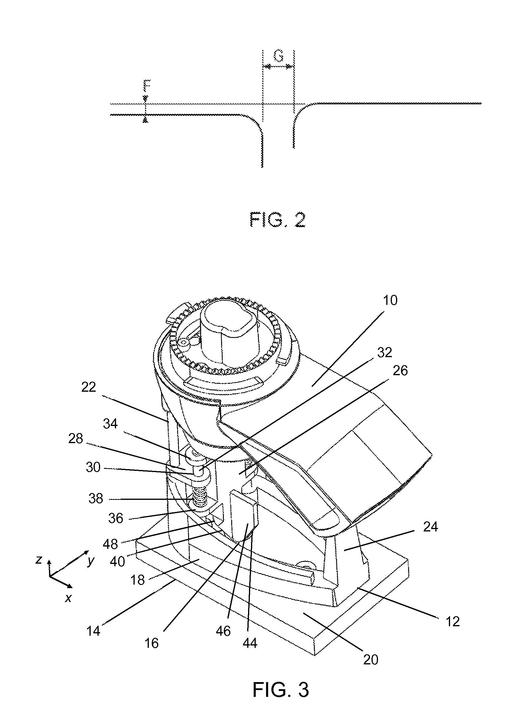
[0031]The embodiments discussed below may be applied as an enhancement to a conventional optical triangulation sensor, e.g. the GapGun sensor manufactured by Third Dimension Software Limited, mentioned above.

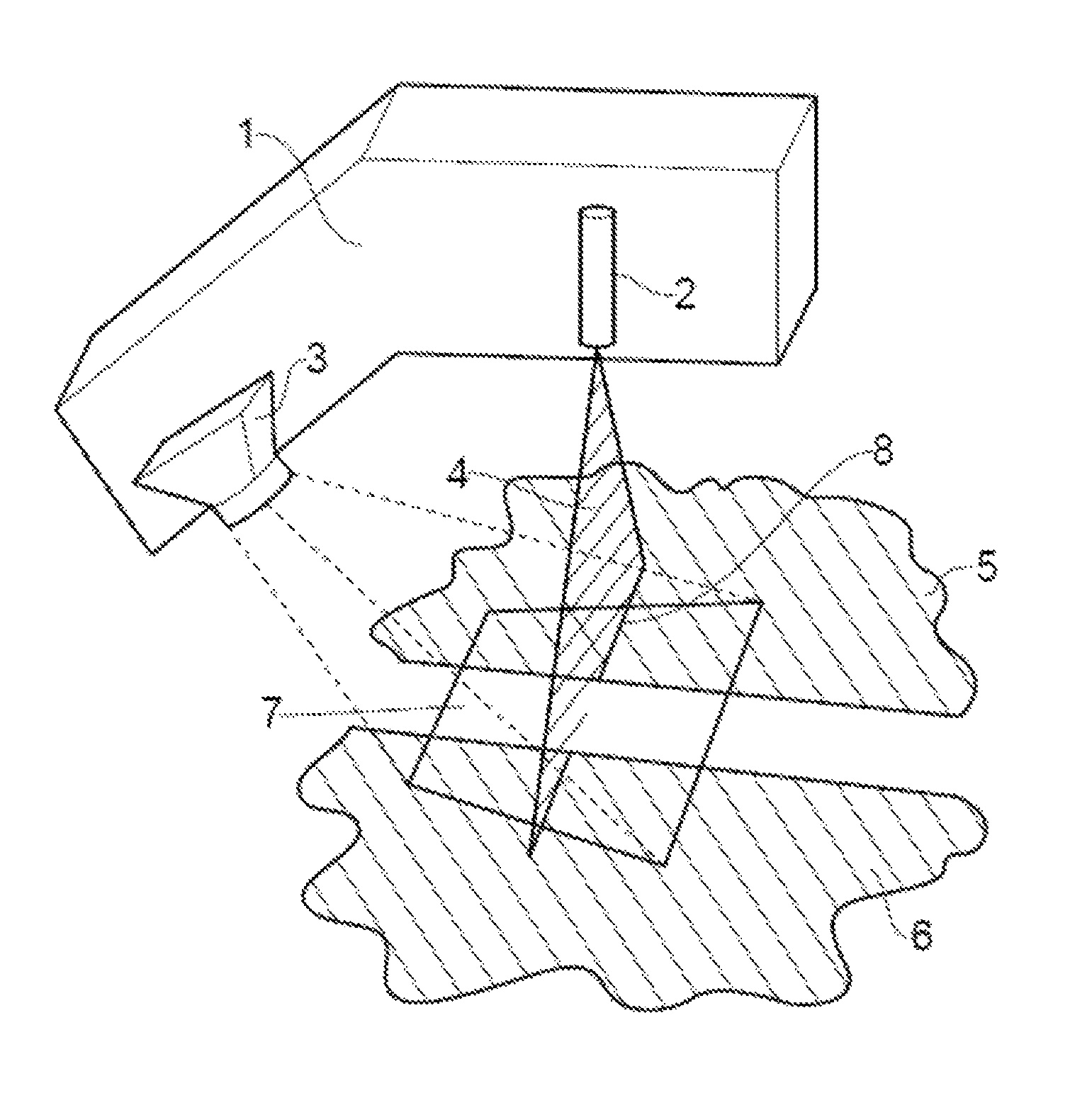
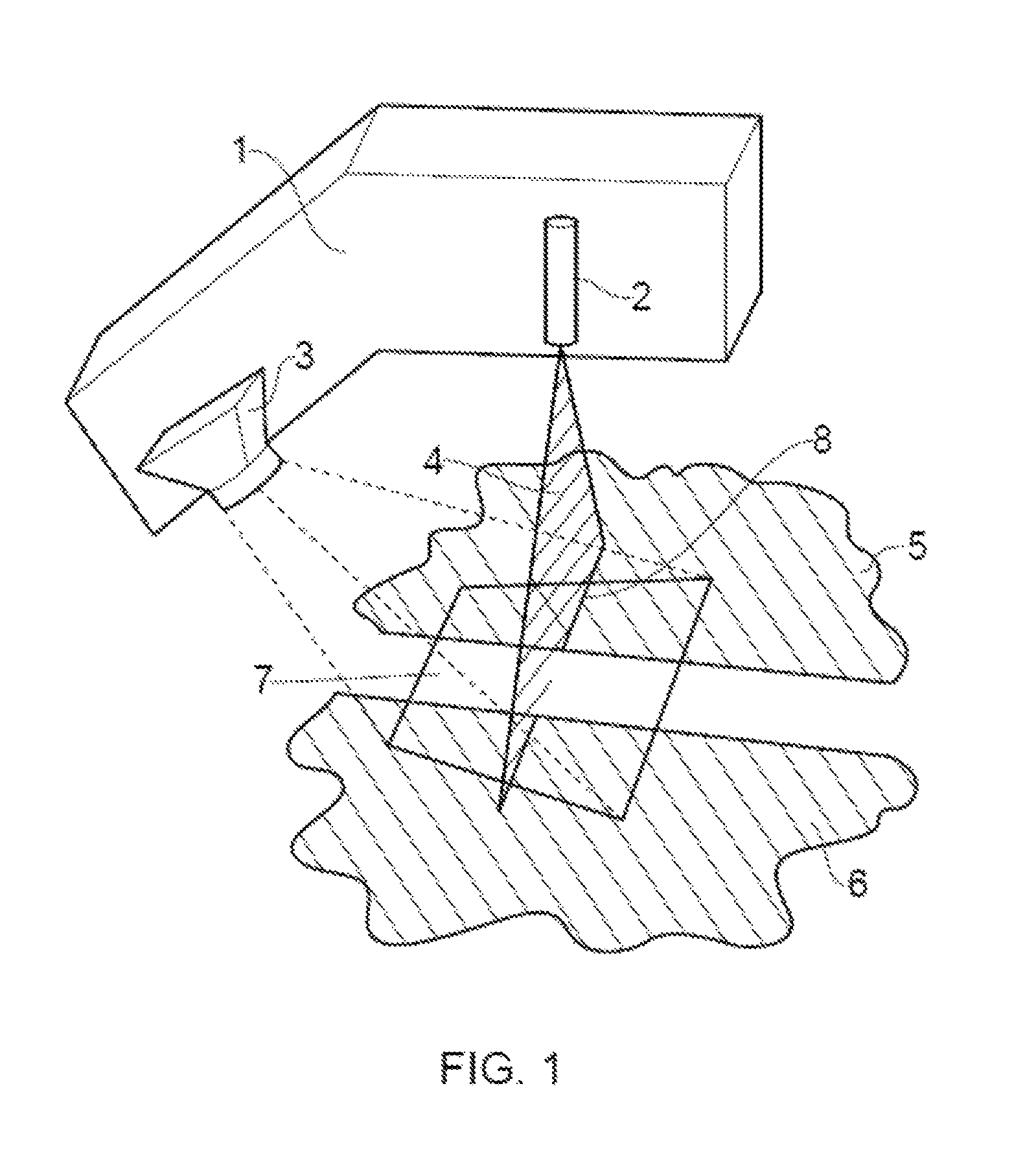
[0032]FIGS. 3 and 4 shows a optical triangulation sensor 10 having a positioning device 12 that is an embodiment of the invention mounted on a workpiece 14 that has a countersunk hole 16 formed therein. The positioning device 12 comprises a platform 18 whose underside engages the top surface 20 of the workpiece 14. The platform 18 comprises a frame that defines an aperture through which the top surface 20 is visible. The platform 18 have a pair of upstanding front struts 22 and a rear strut 24 for attaching to opposite ends of the optical triangulation sensor 10. The optical triangulation sensor 10 is therefore secured in a fixed position with respect to the platform 18. The fixed position is such that a planar light beam emitted by a light sourc...


PUM


Abstract

The invention provides a positioning device for locating a planar light beam emitted by an optical triangulation sensor across a diameter of a hole formed in a surface of an object. The positioning device has an adjustable guiding element which is capable of locating an optical triangulation sensor at the same distance away from holes have a range of diameters. The guiding element is movably mounted relative to a platform that is fixed to the optical triangulation sensor. The guiding element comprises a body which is insertable into the hole, the body having a pair of contact surfaces for contacting diametrically opposed portions of the hole, the pair of contact surfaces being opposed to each other in a direction orthogonal to the plane of the planar light beam.

Description

FIELD OF THE INVENTION[0001]This invention relates to measurement apparatus which uses triangulation principles to measure the physical geometry of articles and / or their relative position to each other. For example, the invention may be used with a laser triangulation sensor. In particular, the present invention concerns positioning the planar light beam of an optical triangulation sensor with respect to a feature on a measurement surface to facilitate interpretation of a captured image.BACKGROUND TO THE INVENTION[0002]Optical measurement systems which use a laser triangulation sensor to obtain dimensional information about objects are known. For example, such systems may be arranged to determine the distance of objects from the sensor or the profile of objects within the field of view of the sensor.[0003]Referring to FIG. 1, a conventional laser triangulation measurement device 1 comprises a light source 2 e.g. laser which is arranged to project a planar beam 4 (e.g. sheet) of ligh...

Claims


Application Information

Patent Timeline
Patent Type & Authority Patents(United States)
IPC IPC(8): G01B11/14G01B11/02G01B11/25G01S17/48
CPCG01B11/25G01B11/026G01S17/48
Inventor MONKS, TIM
Owner THIRD DIMENSION SOFTWARE
Why Eureka
Try Eureka