Eureka AIR delivers breakthrough ideas for toughest innovation challenges, trusted by R&D personnel around the world.

Behavior control system

a behavior control and behavior technology, applied in the field of behavior control systems, can solve the problems of difficulty in generating the trajectory of a state variable, temporarily stopping the agent, and affecting the continuity of the behavior, and achieve the effect of high degree of accuracy

Active Publication Date: 2015-04-21
HONDA MOTOR CO LTD
View PDF9 Cites 3 Cited by
  • Summary
  • Abstract
  • Description
  • Claims
  • Application Information

AI Technical Summary

Benefits of technology

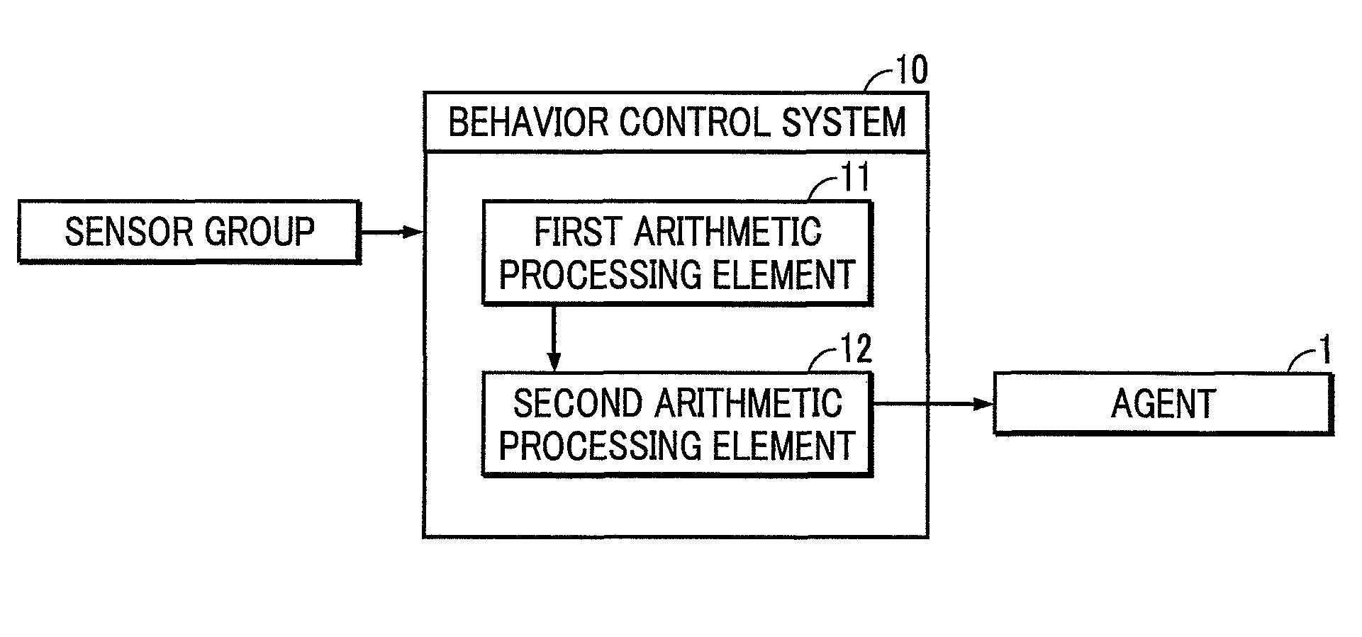
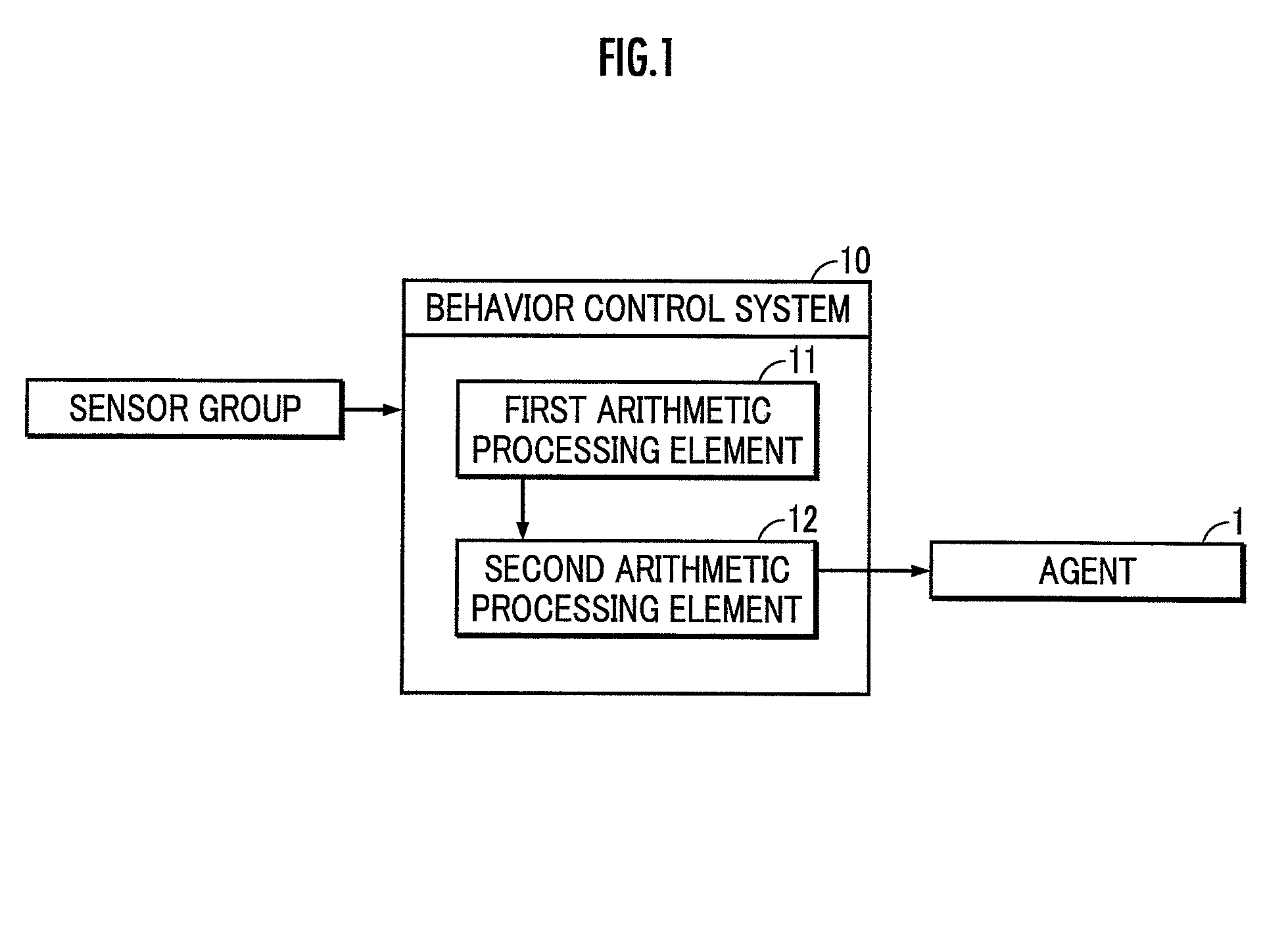
[0009]One state variable trajectory which the agent 1 follows among the plurality of state variable trajectories is generated as a desired state variable trajectory if it maximizes or optimizes the joint probability of the stochastic transition model. The desired state variable trajectory is generated on the basis of the stochastic transition model as described above. Therefore, the behavior of the agent accompanied by an interaction with the object is able to be controlled so that the continuity of the state variables representing the state of the object 2 is secured. As a result, while the executability of each subtask secures the continuity of behavior of the agent in time series, the behavior control system is able to cause the agent to execute a plurality of different subtasks continuously.
[0010]Preferably, the first arithmetic processing element is configured to generate a plurality of i-th state variable trajectories which represent time series of the state variable of the object according to an i-th stochastic transition model in which the transition mode of the state variable is determined depending on each execution probability of a subtask having an i-th execution order (i=1, 2, - - - ) and a subtask having an (i+1)-th execution order among the plurality of subtasks; and the second arithmetic processing element is configured to generate one i-th state variable trajectory which maximizes or optimizes a joint probability of a whole of the i-th stochastic transition model, as an i-th desired state variable trajectory, among the plurality of i-th state variable trajectories generated by the first arithmetic processing element, and to generate a connection trajectory of the i-th desired state variable trajectory as the desired state variable trajectory.
[0011]According to the behavior control system having the above configuration, only two subtasks are taken into consideration among a plurality of subtasks in each stochastic transition model. Therefore, the behavior control system is able to cause the agent to continuously execute the plurality of different subtasks while securing the continuity of behavior of the agent in parallel with a reduction in arithmetic processing load required for the generation of the state variable trajectory according to each stochastic transition model or with a decrease in arithmetic processing time.
[0013]According to the behavior control system having the above configuration, an environmental factor, which is an uncertain element, is able to be estimated with a high degree of accuracy on the basis of the generation result of the desired state variable trajectory. The subsequent stochastic transition models are selected or constructed on the basis of the estimation result, thereby enabling the generation of a desired state variable trajectory which reflects the state of the object based on the actual environmental factor.

Problems solved by technology

In the case of causing the agent to execute a task composed of a series of different subtasks in a continuous manner, however, it is difficult to generate the trajectory of a state variable while adaptively setting the time point of switch between the subtasks.
Therefore, the continuity of the behavior might be impaired such that the operation of the agent temporarily stops at the time of switch between the subtasks.

Method used


Image

  • Behavior control system
  • Behavior control system
  • Behavior control system

Examples


first embodiment

[0031][First Embodiment]

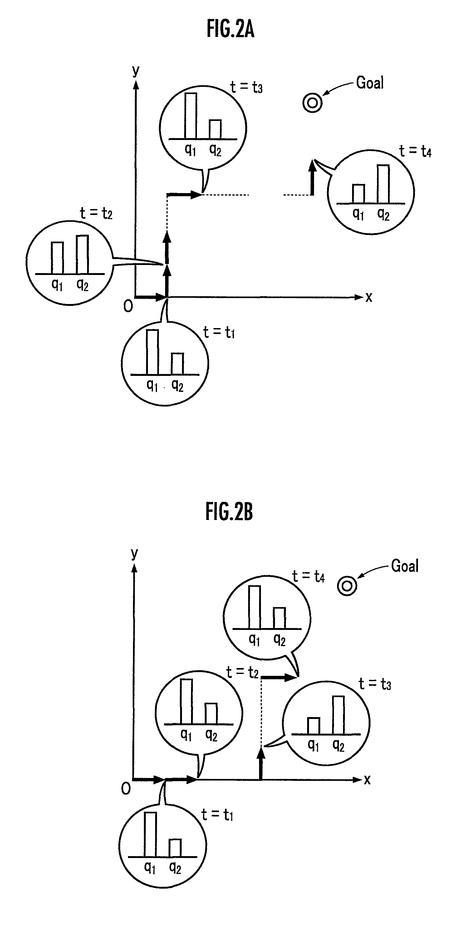
[0032]As a plurality of subtasks, an end effector attached to the tip of an arm robot as the agent 1 adopts a first subtask which moves the object 2 in the +x direction by a predetermined amount in the xy-coordinate system and a second subtask which moves the object 2 in the +y direction by a predetermined amount in the xy-coordinate system (See FIGS. 2A and 2B). The initial state of the object 2 is defined by the origin coordinate value (0, 0) of the xy-coordinate system.

[0033](Stochastic Transition Model)

[0034]The stochastic transition model is defined by state variables of the object 2 illustrated in Table 1 and variables representing execution subtasks illustrated in Table 2.

[0035]

TABLE 1Xx-coordinate value of object 2Yy-coordinate value of object 2ΔxAmount of translation of object 2 in x directionΔyAmount of translation of object 2 in y direction

[0036]

TABLE 2S11if argmax (qi) = q10ElseS21if argmax (qi) = q20Else

[0037]Specifically, the stochastic transiti...

second embodiment

[0055][Second Embodiment]

[0056]The first subtask (roll) is a task of tilting the object 2 so as to lift the undersurface (bottom surface) of the object 2 placed on a first floor surface from the first floor surface with one side of the undersurface of the object 2 as an axis line (See FIG. 5A). The term “floor surface” is not limited to the floor surface of a building structure or the like, but means an upper surface of all kinds of structural object such as the upper surface of a desk, a road surface, a ground surface, or the like.

[0057]The second subtask (slide) is a task of translationally moving the object 2 with one side of the undersurface abuts against the first floor surface while maintaining the tilting posture of the object 2 achieved by the execution of the first subtask (See FIG. 5B).

[0058]The third subtask (hump) is a task of tilting the object 2 so that a part of the undersurface of the object 2 abuts against a second floor surface, which is higher by one step than a f...


PUM


Abstract

A system capable of causing an agent to continuously execute a plurality of different subtasks while securing the continuity of behavior of the agent is provided. A plurality of state variable trajectories representing the time series of a state variable of an object are generated according to a stochastic transition model in which the state variable of the object is represented as a random variable. The stochastic transition model is defined so that the transition mode of the state variable is determined according to an execution probability of each subtask in which a probability distribution is represented by a Dirichlet distribution. An operation of the agent is controlled so that the state of the object transits according to one state variable trajectory (desired state variable trajectory) maximizing or optimizing the joint probability of a whole of the stochastic transition model among the plurality of state variable trajectories.

Description

BACKGROUND OF THE INVENTION[0001]1. Field of the Invention[0002]The present invention relates to a system which controls the behavior of a robot to cause the robot to execute a plurality of subtasks.[0003]2. Description of the Related Art[0004]There has been proposed a technical method in which a state variable defining the behavior of an agent is defined by a continuous random variable in order to secure the continuity of the behavior of the agent and the behavior of the agent is controlled according to the trajectory of the state variable (Refer to Japanese Patent Application Laid-Open No. 2010-005761 and Japanese Patent Application Laid-Open No. 2011-148081).[0005]In the case of causing the agent to execute a task composed of a series of different subtasks in a continuous manner, however, it is difficult to generate the trajectory of a state variable while adaptively setting the time point of switch between the subtasks. Therefore, the continuity of the behavior might be impaired...

Claims


Application Information

Patent Timeline
Patent Type & Authority Patents(United States)
IPC IPC(8): G05B19/18B25J9/16
CPCB25J9/163B25J9/161G05B2219/33054
Inventor IBA, SOSHIHAYASHI, AKINOBU
Owner HONDA MOTOR CO LTD
Why Eureka
Eureka Blog
Learn More