

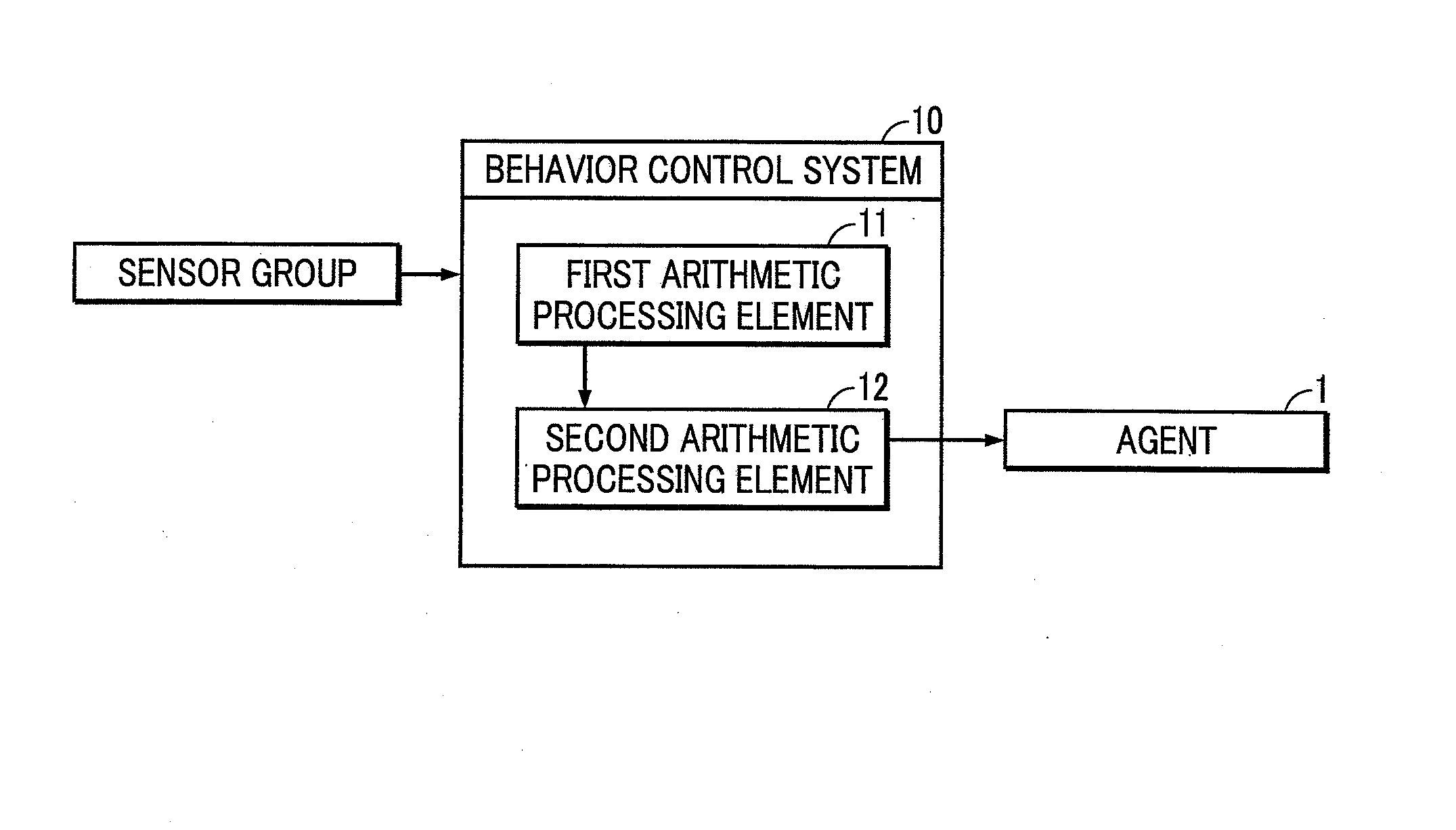
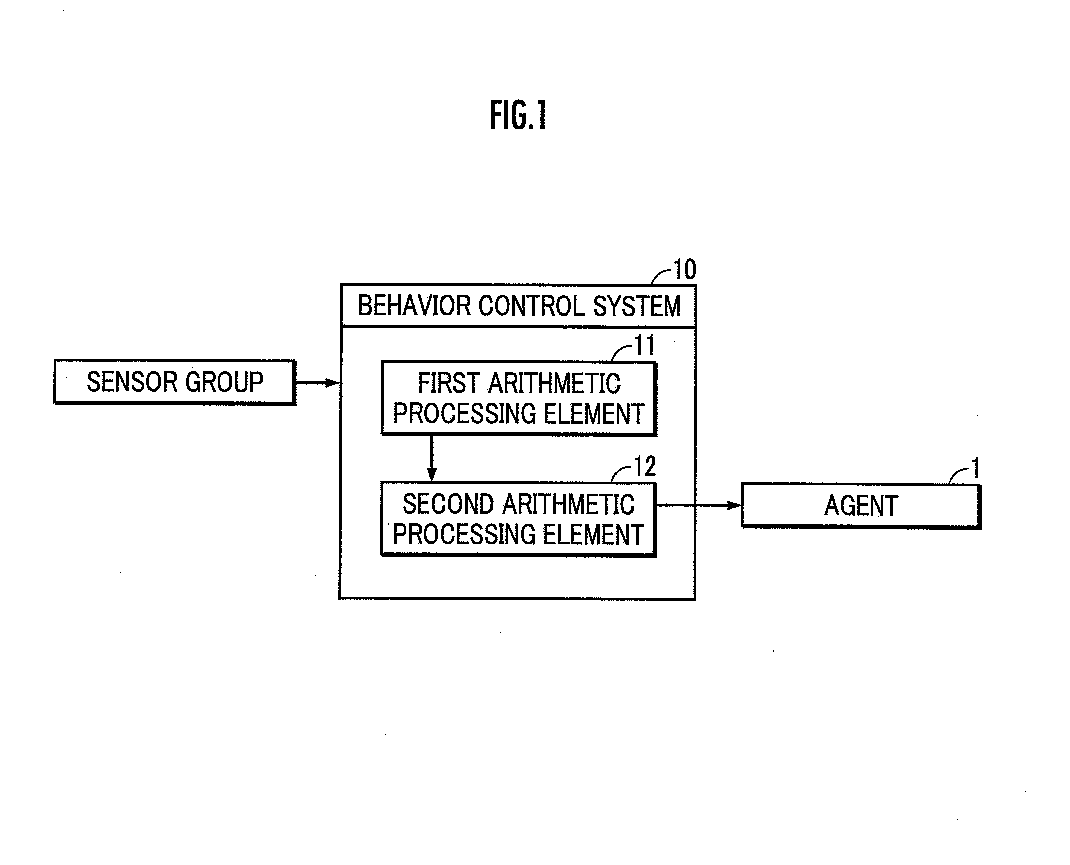
Behavior control system
a behavior control and behavior technology, applied in the field of behavior control systems, can solve the problems of difficulty in generating the trajectory of a state variable, temporarily stopping the agent, and affecting the continuity of the behavior, and achieve the effect of high degree of accuracy
- Summary
- Abstract
- Description
- Claims
- Application Information
AI Technical Summary
Benefits of technology
Problems solved by technology
Method used
Image

Examples
first embodiment
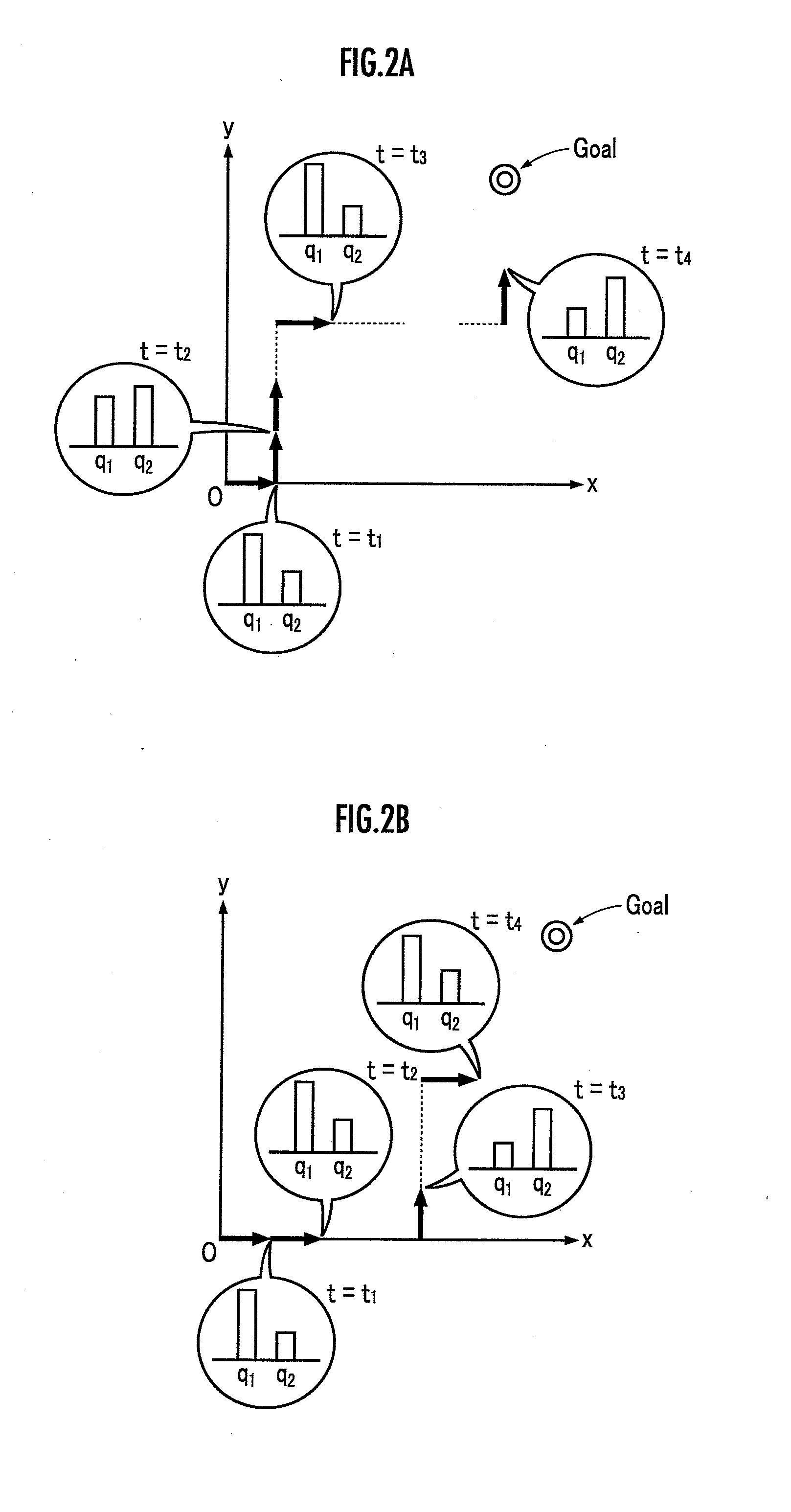
[0031]As a plurality of subtasks, an end effector attached to the tip of an arm robot as the agent 1 adopts a first subtask which moves the object 2 in the +x direction by a predetermined amount in the xy-coordinate system and a second subtask which moves the object 2 in the +y direction by a predetermined amount in the xy-coordinate system (See FIGS. 2A and 2B). The initial state of the object 2 is defined by the origin coordinate value (0, 0) of the xy-coordinate system.
[0032](Stochastic Transition Model)
[0033]The stochastic transition model is defined by state variables of the object 2 illustrated in Table 1 and variables representing execution subtasks illustrated in Table 2.
TABLE 1Xx-coordinate value of object 2Yy-coordinate value of object 2ΔxAmount of translation of object 2 in x directionΔyAmount of translation of object 2 in y direction
TABLE 2S11if argmax (qi) = q10ElseS21if argmax (qi) = q20Else
[0034]Specifically, the stochastic transition model is defined by relational ex...
second embodiment
[0052]The first subtask (roll) is a task of tilting the object 2 so as to lift the undersurface (bottom surface) of the object 2 placed on a first floor surface from the first floor surface with one side of the undersurface of the object 2 as an axis line (See FIG. 5A). The term “floor surface” is not limited to the floor surface of a building structure or the like, but means an upper surface of all kinds of structural object such as the upper surface of a desk, a road surface, a ground surface, or the like.
[0053]The second subtask (slide) is a task of translationally moving the object 2 with one side of the undersurface abuts against the first floor surface while maintaining the tilting posture of the object 2 achieved by the execution of the first subtask (See FIG. 5B).
[0054]The third subtask (hump) is a task of tilting the object 2 so that a part of the undersurface of the object 2 abuts against a second floor surface, which is higher by one step than a first floor surface, with ...
PUM
 Abstract
Description
Claims
Application Information