
Method for assisted positioning of an organ on a platform of a medical imaging system

a technology of medical imaging and assisted positioning, which is applied in the direction of patient positioning for diagnostics, instruments, applications, etc., can solve the problems of not being able to know which parts of the breast, not being able to correctly position the breast, and not being able to remedy the lack of information on a breast part in the acquired image, etc., to achieve the effect of easy interpretation and easy implementation

Active Publication Date: 2015-04-28
GENERAL ELECTRIC CO
View PDF19 Cites 14 Cited by
  • Summary
  • Abstract
  • Description
  • Claims
  • Application Information

AI Technical Summary

Benefits of technology

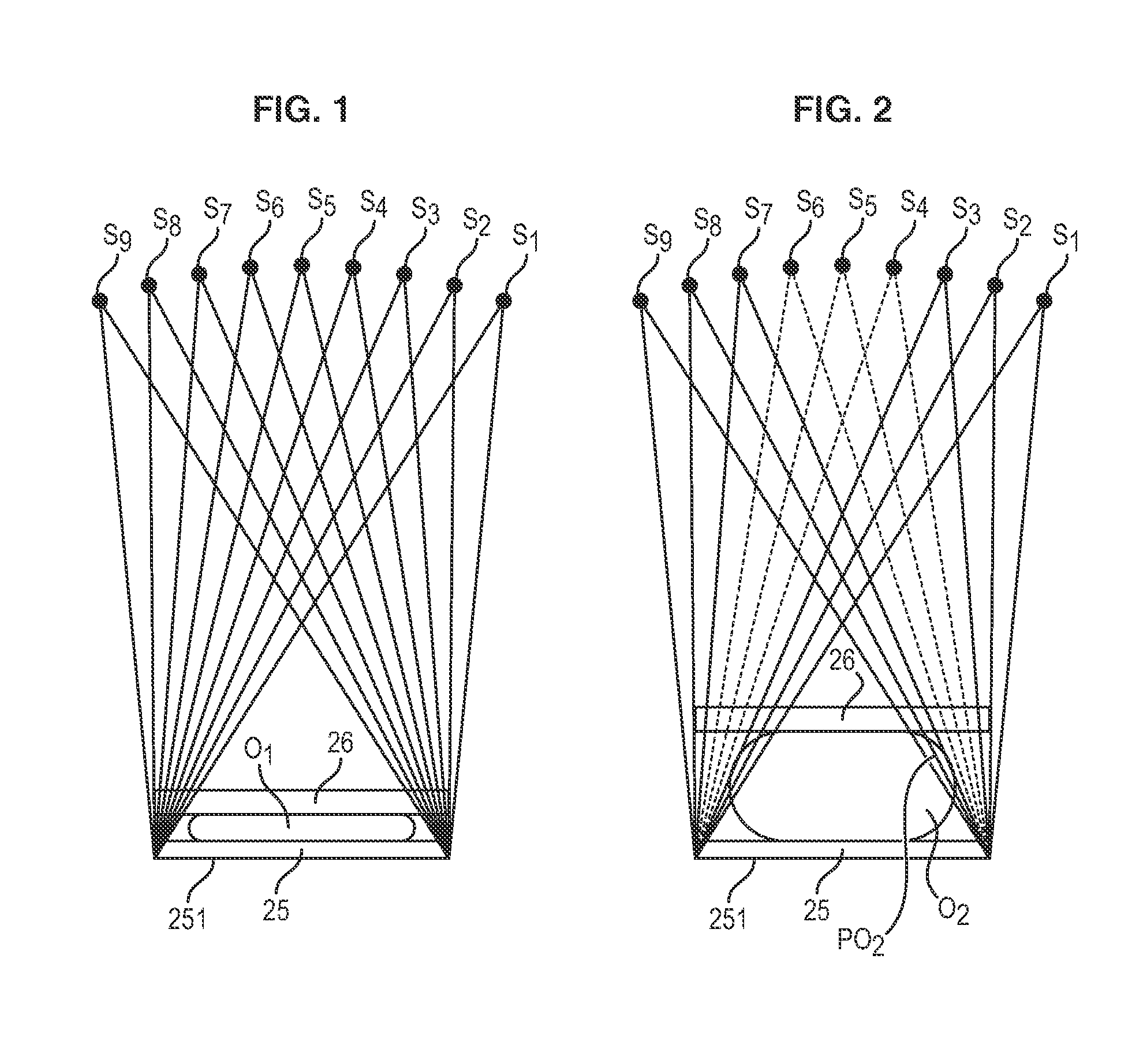
[0019]The operator in charge of positioning the patient, and hence the organ to be imaged, is provided with a visual aid that is easily interpreted for determining which portion of space above the detector will be illuminated by the X-ray source at all positions thereof.
[0020]In addition, this method does not require major modifications to the acquisition system. It is therefore easy to implement.

Problems solved by technology

It is therefore not possible to know which parts of the breast will be irradiated by the X-ray source at all the positions thereof.
Therefore, if the positions of the breast are simply controlled in the same way as for conventional 2D mammography, it will only be possible to position the breast correctly for one single position of the X-ray source.
This problem particularly occurs during radiography in cranio-caudal mode (CC—the detector lies parallel to the floor) with respect to the two side lobes of the breast, and in mediolateral-oblique mode (MLO—the detector lies 45° to the vertical) with respect to the lower breast lobe.
At the present time, no method is available to remedy the lack of information on a part of the breast in the acquired images.

Method used


Image

  • Method for assisted positioning of an organ on a platform of a medical imaging system
  • Method for assisted positioning of an organ on a platform of a medical imaging system
  • Method for assisted positioning of an organ on a platform of a medical imaging system

Examples


Embodiment Construction

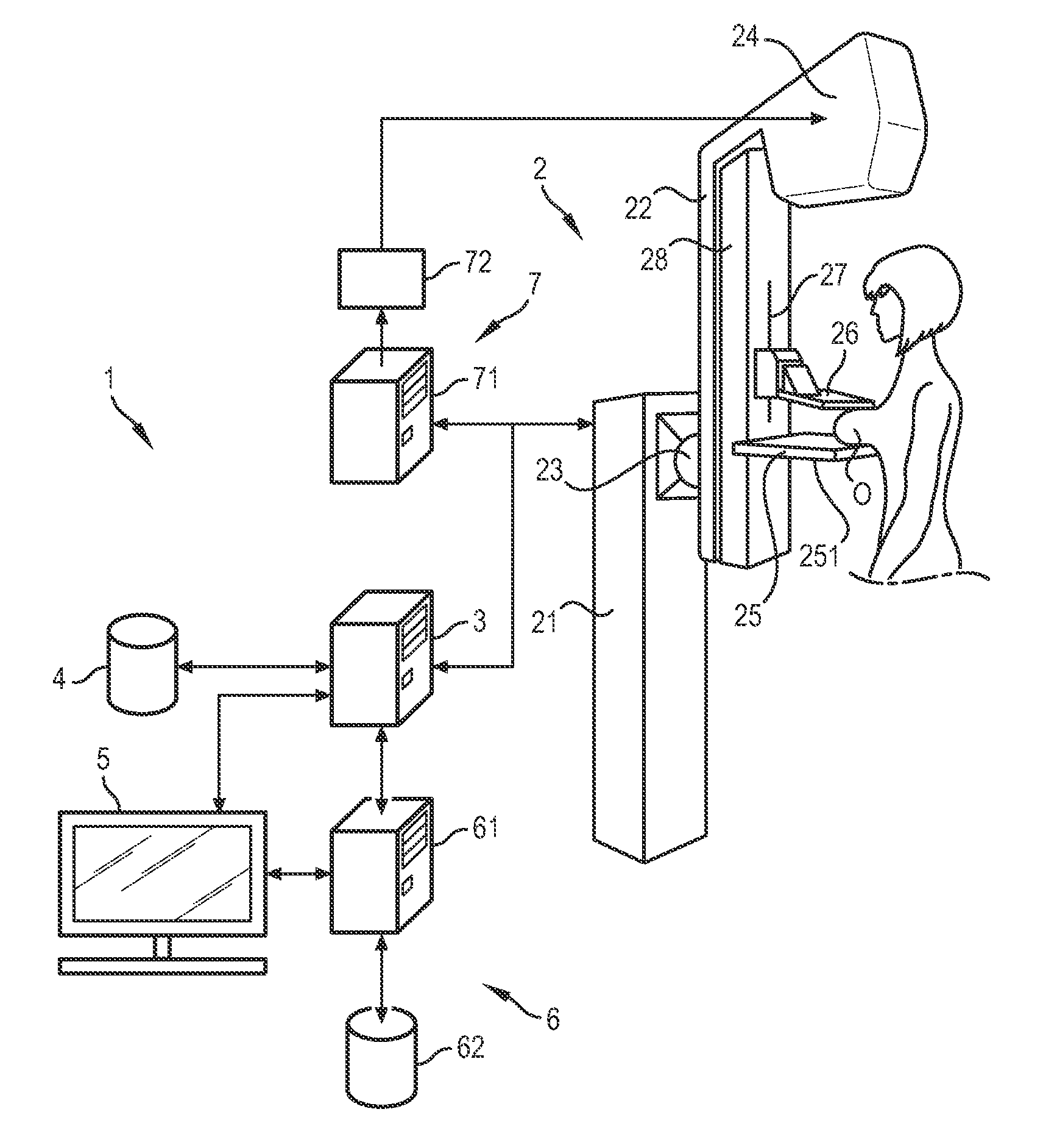
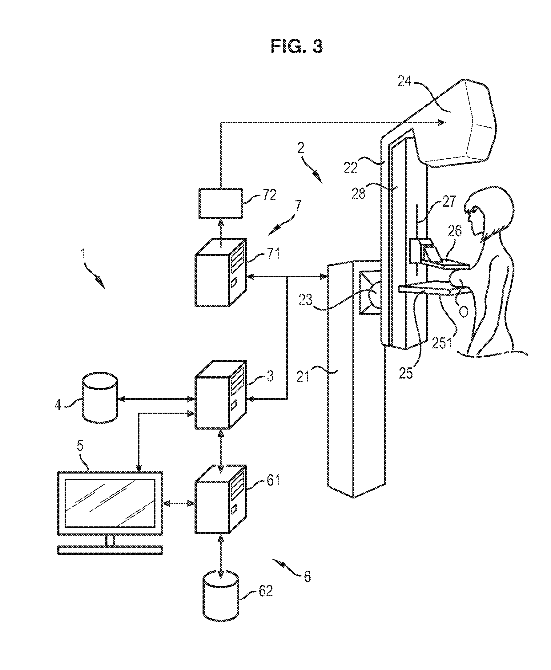
[0032]FIGS. 3 and 4 schematically illustrate a medical imaging system 1 for the acquisition of images allowing three-dimensional (3D) reconstruction of a breast O from two-dimensional images (2D) of the breast O. The medical imaging system 1 is shown coupled with a module for generating images evidencing suspect regions of the breast O.

[0033]The medical imaging system 1 may be mammography equipment for the detection and characterization of radiological signs for the screening, diagnosis and treatment of breast cancer (tissue matrix).

[0034]The medical imaging system 1 comprises a 2D image acquisition unit 2. The acquisition unit 2 chiefly comprises a detector 251 lying opposite a radiation source and illuminated by the latter during the acquisition of medical images. The radiation source is mobile relative to the detector 251. Optionally, the detector 251 may also be mobile relative to the radiation source.

[0035]A more thorough example of an acquisition system 1 is given below.

[0036]...


PUM


Abstract

A method for assisted positioning of an organ is provided. An acquisition system comprises a platform underneath which a detector is placed for the acquisition of radiographic medical images, during which a radiation source is moved over different successive positions with respect to the detector, wherein at least one medical image is acquired at each position of the radiation source. The method comprises illuminating the platform with a light source of the acquisition system to assist the positioning of the organ on the platform; and determining, with a drive unit of the acquisition system, a positioning limit on the platform based on the distance separating the platform and a compression paddle used to compress the organ and based on the position of the light source relative to the detector, wherein the positioning limit on the platform is a limit beyond which the organ must not lie.

Description

BACKGROUND OF THE INVENTION[0001]1. Field of the Invention[0002]Embodiments of the present invention relate to the field of radiography using tomosynthesis, and more particularly the field of methods for assisted positioning of an organ, e.g. a breast, for a radiography session by tomosynthesis.[0003]2. Description of the Prior Art[0004]Mammography is conventionally two-dimensional radiography. The patient's breast is positioned on a breast platform with respect to a harmless radiation light source, and then compressed by a compression paddle. The breast is positioned so that it is entirely irradiated by the rays of the X-ray source, i.e. an imaged field illuminated by the light source is the same as the field illuminated by the X-ray source.[0005]For this purpose, when positioning the breast, the imaged field and the breast are illuminated by a light source. Since the light source and the X-ray source cannot physically occupy the same position, a mirror is provided to deflect the l...

Claims


Application Information

Patent Timeline
Patent Type & Authority Patents(United States)
IPC IPC(8): G03B42/02A61B6/04A61B6/02A61B6/00A61B6/08
CPCA61B6/502A61B6/025A61B6/04A61B6/547A61B6/08A61B6/0414
Inventor POPOVA, YANASOUCHAY, HENRI
Owner GENERAL ELECTRIC CO
Learn More