Self-cleaning air filtration system

Active Publication Date: 2015-05-05
ENG LABS LLC
View PDF2 Cites 1 Cited by
  • Summary
  • Abstract
  • Description
  • Claims
  • Application Information

AI Technical Summary

Benefits of technology

The invention is about a device that filters air by using high pressure air to remove contaminants from the air. The device includes a chamber that briefly reversely flows high pressure air through the filter media to remove any particles that may become dislodged during operation. This allows for a quick and complete removal of the contaminants without causing any significant interruption in the operation of the device.

Problems solved by technology

High efficiency filters remove a large proportion of contaminants, but will quickly become clogged due to buildup of the contaminants on the filter media since a great proportion of the contaminants in the air flow will be filtered out.
Much labor would be required to keep such filters clear by manual removal of the build up of contaminants captured by the filter media.
However, the inclusion of additional prefilters will add to the maintenance costs of the system.
This approach interrupts normal air flow for a significant time and requires a substantial volume of reverse flow through the filter media and a purging flow through the space just upstream of the filter media.
This approach minimizes the interruption of normal operation, but is even more likely to result in dislodged contaminants being drawn to the filter media after normal flow through the filter is restored as described above, since only a brief reverse flow occurs, and all of the contaminants will likely not have a chance to settle out away from the filter media before restarting normal air flow.

Method used


Image

  • Self-cleaning air filtration system
  • Self-cleaning air filtration system
  • Self-cleaning air filtration system

Examples


Embodiment Construction

[0016]In the following detailed description, certain specific terminology will be employed for the sake of clarity and a particular embodiment described in accordance with the requirements of 35 USC 112, but it is to be understood that the same is not intended to be limiting and should not be so construed inasmuch as the invention is capable of taking many forms and variations within the scope of the appended claims.

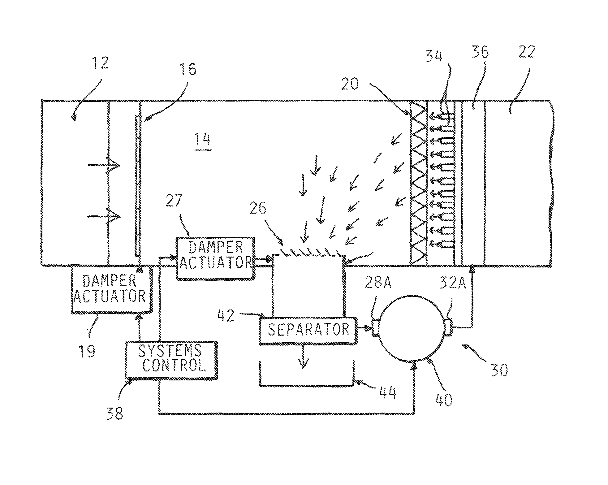
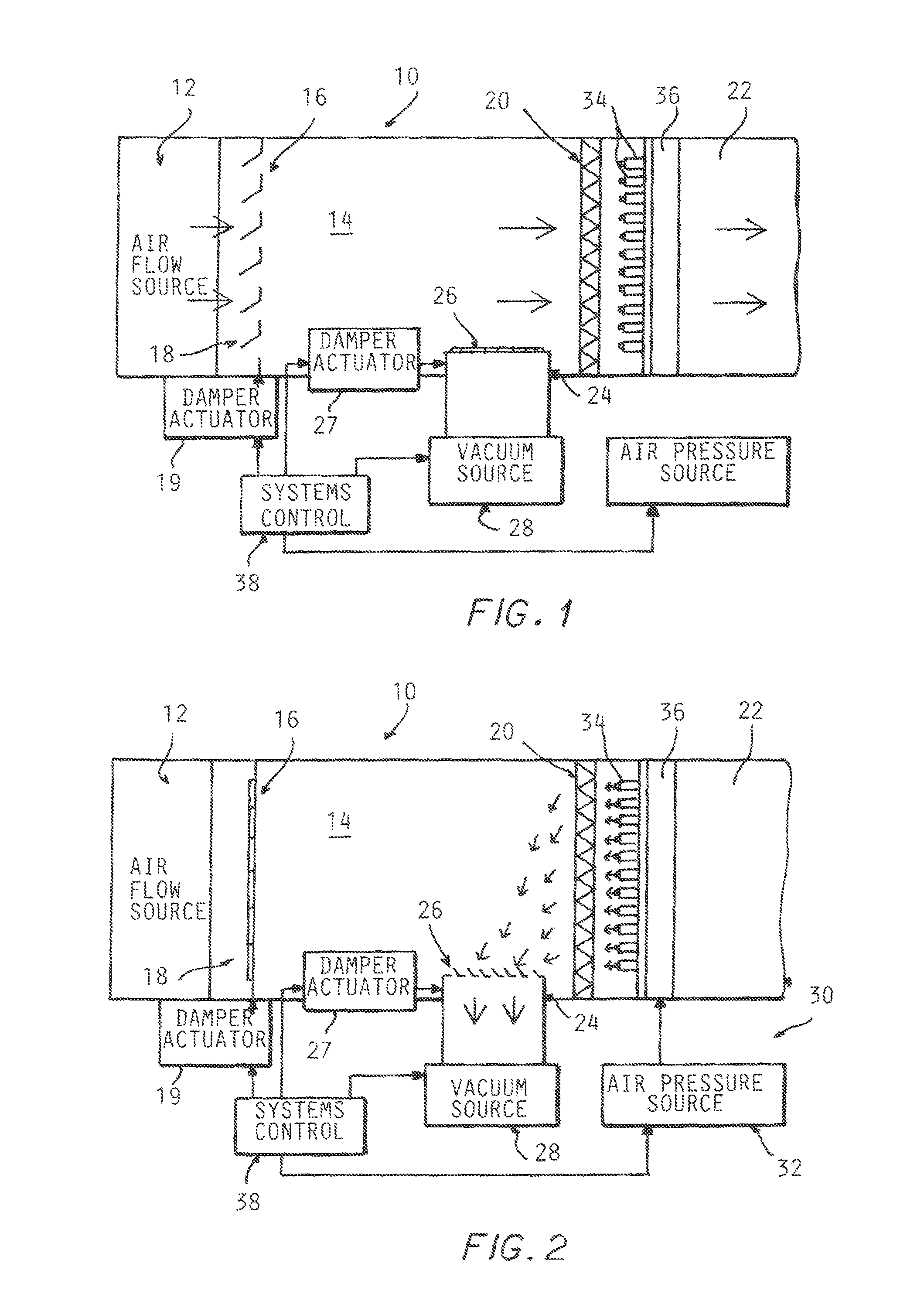
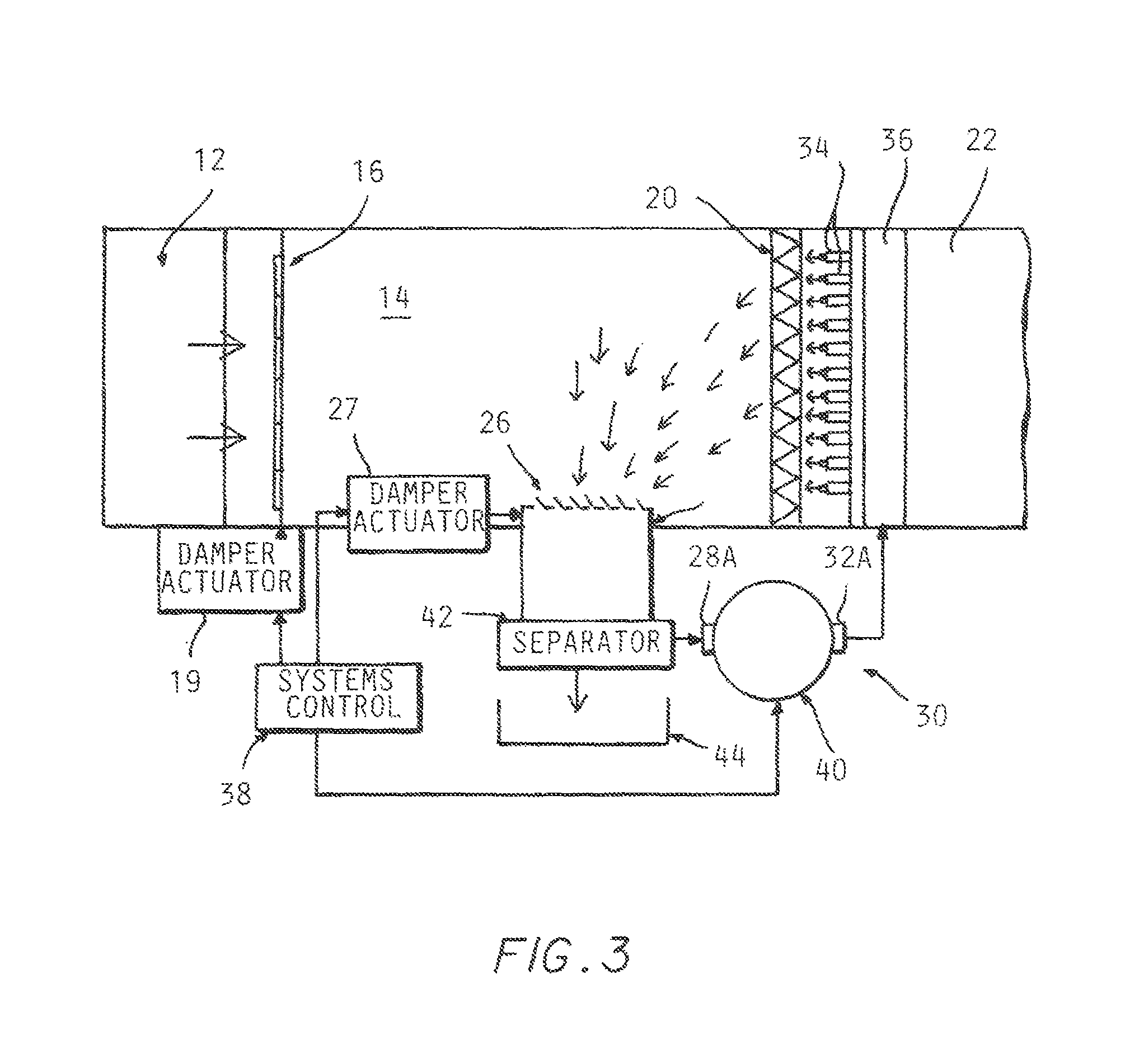
[0017]Referring to the drawings, a self-cleaning filtration section 10 of an air flow system according to the invention is depicted diagrammatically in its normal operating state, in which a sustained air flow from a source 12 is directed into an antechamber 14 adjacent a filter media on the inlet side thereof.

[0018]A damper mechanism 16 including an actuator 17 is provided which is normally open but is controllably operable to close off an air inlet 18 at the inlet end of the antechamber 14 which receives the air flow to be filtered.

[0019]The filter media 20 is disposed...


PUM

PropertyMeasurementUnit
Flow rateaaaaaaaaaa
Lengthaaaaaaaaaa
Widthaaaaaaaaaa

Abstract

A self-cleaning system and method for removing contaminants captured by an air flow filter media in which a reverse air flow is directed back through the filter media and into an antechamber which is closed during self-cleaning and a vacuum source is connected to the antechamber to quickly evacuate the air in said antechamber containing dislodged contaminants suspended therein.

Description

BACKGROUND OF THE INVENTION[0001]This invention concerns air filtration such as is used in HVAC and industrial air filtration and dust collection systems.[0002]High efficiency filters remove a large proportion of contaminants, but will quickly become clogged due to buildup of the contaminants on the filter media since a great proportion of the contaminants in the air flow will be filtered out.[0003]Much labor would be required to keep such filters clear by manual removal of the build up of contaminants captured by the filter media.[0004]For this reason, disposable or cleanable prefilters are often used to remove the larger contaminants from the air stream in order to reduce the servicing requirements for the more costly high efficiency filters. However, the inclusion of additional prefilters will add to the maintenance costs of the system.[0005]Self-cleaning air filters are well known which typically carry out cleaning by establishing a reverse air flow through the filter media to d...

Claims


Application Information

Patent Timeline
IPC IPC(8): B01D46/00
CPCB01D46/0068B01D46/48B01D2273/28B01D46/71
Inventor ELLIOTT, CORY
Owner ENG LABS LLC
Why Eureka
Try Eureka