Managing environmental control system efficiency

a technology of environmental control system and efficiency, applied in process and machine control, nuclear engineering, nuclear elements, etc., can solve the problems of heating and air conditioning system occasionally needing maintenance, increasing cost of those energy sources, and wasting costly energy

Active Publication Date: 2015-05-05
GENERAC POWER SYSTEMS
View PDF26 Cites 8 Cited by
  • Summary
  • Abstract
  • Description
  • Claims
  • Application Information

AI Technical Summary

Problems solved by technology

Today we have reliable energy sources such as electricity, gas and fuel oil for powering heating and air conditioning, although the cost of those energy sources keeps rising.
As a result, these comforts are often taken for granted and may run inefficiently without that inefficiency being noticed by the user, thereby wasting costly energy.
For example, heating and air conditioning systems occasionally require maintenance due to dirty filters, low refrigerant, lack of engine lubrication, etc.
Running an air conditioner or heater in these conditions reduces efficiency and increases the likelihood of system failure, often at the most inopportune times when the system is most stressed.

Method used


Image

  • Managing environmental control system efficiency
  • Managing environmental control system efficiency
  • Managing environmental control system efficiency

Examples


first embodiment

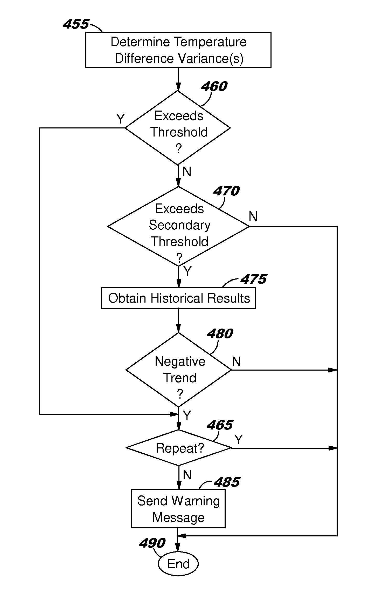
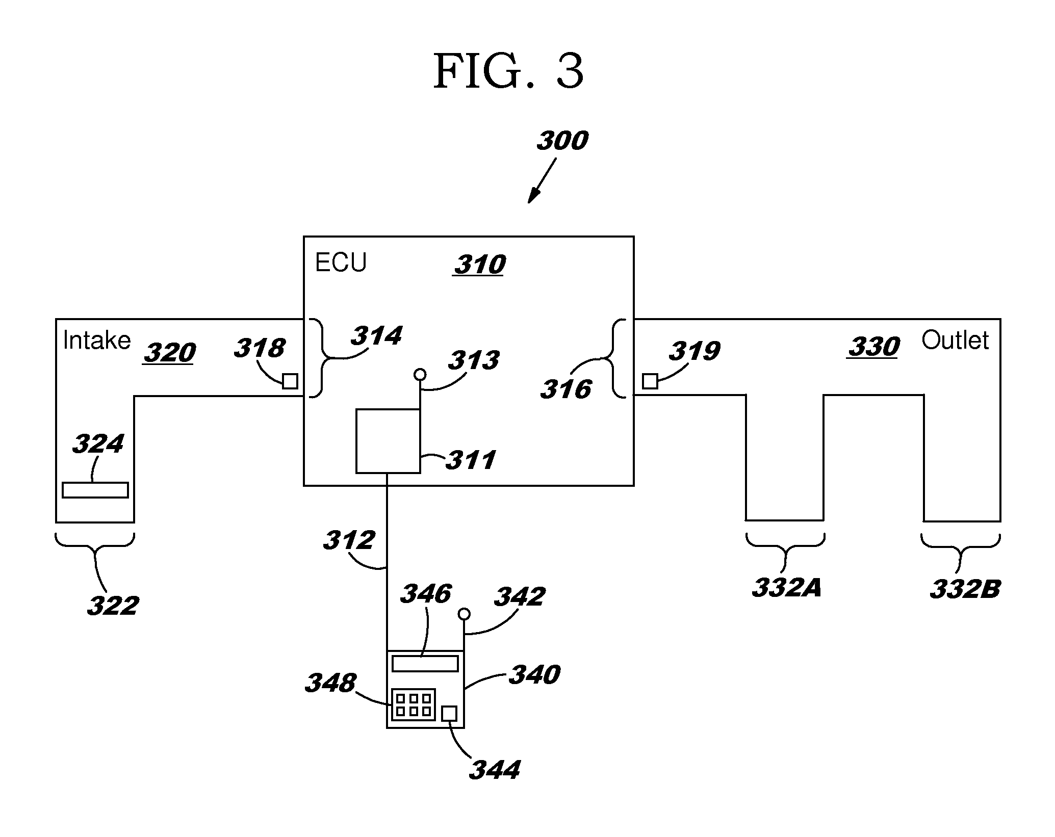
[0029]FIG. 3 depicts a block diagram of an environmental control system 300 in accordance with a This embodiment may be implemented within an environmental control unit from the factory. Environmental control system 300 includes an environmental control unit 310, an air intake plenum 320, an air outlet plenum 330 and an external control unit 340. As described above, an environmental control unit may include and air conditioning unit, a heating unit, or both. If both, it is often referred to as a HVAC (heating, ventilation and air conditioning). The operation of environmental control system 300 is described below with reference to FIG. 4.

[0030]Environmental control unit 310 includes an internal control unit 311 which coupled to an external control unit 340. Control units 311 and 340 may be coupled by wire 312 or wirelessly using antennas 313 and 342. Environmental control unit also contains an intake 314 and an outlet 316. Air is drawn into intake 314 through intake plenum 320 such ...

second embodiment

[0041]FIG. 5 depicts a block diagram of an environmental control system 500 in accordance with a This embodiment may be implemented within an environmental control unit during or after installation at a home, business or vehicle. Environmental control system 500 includes an environmental control unit 510, an air intake plenum 520, an air outlet plenum 530 and an external control unit 540. As described above, an environmental control unit may include and air conditioning unit, a heating unit, or both. If both, it is often referred to as a HVAC (heating, ventilation and air conditioning). The operation of environmental control system 500 is described below with reference to FIG. 6.

[0042]Environmental control unit 510 may be coupled to an external control unit 540 by wire 512 or wirelessly to external control unit antenna 542. Environmental control unit contains an intake 514 and an outlet 516. Air is drawn into intake 514 through intake plenum 520 such as by using a fan. The temperat...


PUM


Abstract

A method, system or computer usable program product for providing alerts of inefficiency of an environmental conditioning system including, responsive to a cycle initiation by the environmental conditioning system, measuring a difference between an intake temperature and an outlet temperature after a predetermined period of time, and responsive to the difference being below a minimum level, generating an alert.

Description

BACKGROUND[0001]1. Technical Field[0002]The present invention relates generally to managing an environmental control system, and in particular, to a computer implemented method for managing efficiency for an environmental control system.[0003]2. Description of Related Art[0004]One of the earliest needs of man for comfort was heating and air conditioning. Heating was created when man learned to control fire. Air conditioning was obtained by living in caves. Since those early years, man has sought these comforts throughout the world, often at great expense.[0005]Today we have reliable energy sources such as electricity, gas and fuel oil for powering heating and air conditioning, although the cost of those energy sources keeps rising. In addition, modern heating and air conditioning systems are designed to be highly reliable and will continue performing even when they require maintenance. As a result, these comforts are often taken for granted and may run inefficiently without that ine...

Claims


Application Information

Patent Timeline
Patent Type & Authority Patents(United States)
IPC IPC(8): G08B17/00F24F11/00
CPCF24F11/0086F24F2011/0052F24F2011/0071F24F2011/0075F24F11/30F24F11/32F24F11/58F24F11/46
Inventor HOESL, MARK J.
Owner GENERAC POWER SYSTEMS
Why Eureka
Try Eureka