
Relay node operable with different spatial characteristic antenna patterns

a technology of spatial characteristic and antenna pattern, which is applied in the field of mobile telecommunication network relay nodes, can solve the problems of affecting the overall performance of the telecommunication network, and not being optimal from the indoor coverage point, so as to improve the signal-to-interference ratio and optimize the antenna characteristics.

Inactive Publication Date: 2015-05-05
WSOU INVESTMENTS LLC
View PDF10 Cites 3 Cited by
  • Summary
  • Abstract
  • Description
  • Claims
  • Application Information

AI Technical Summary

Benefits of technology

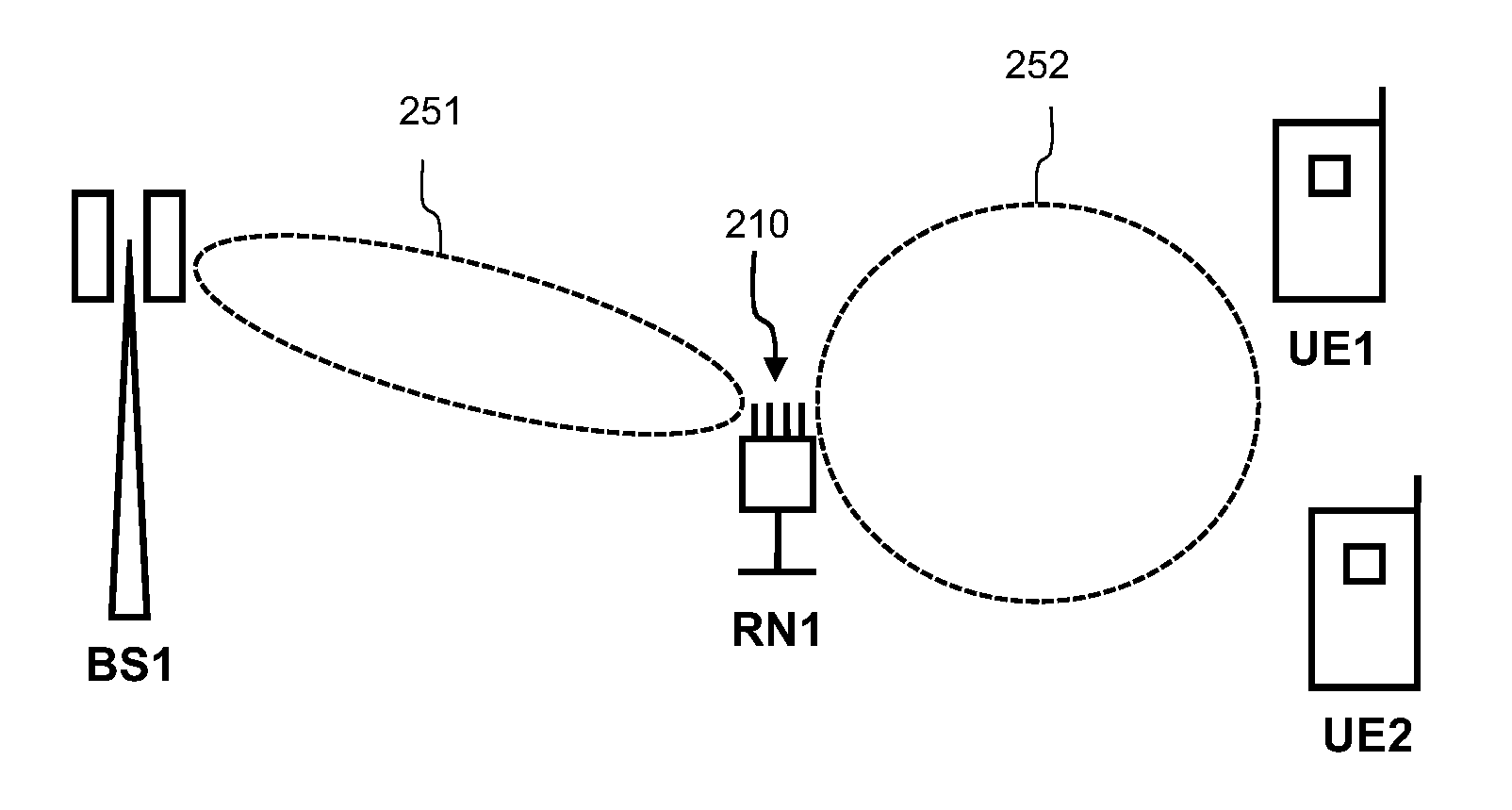
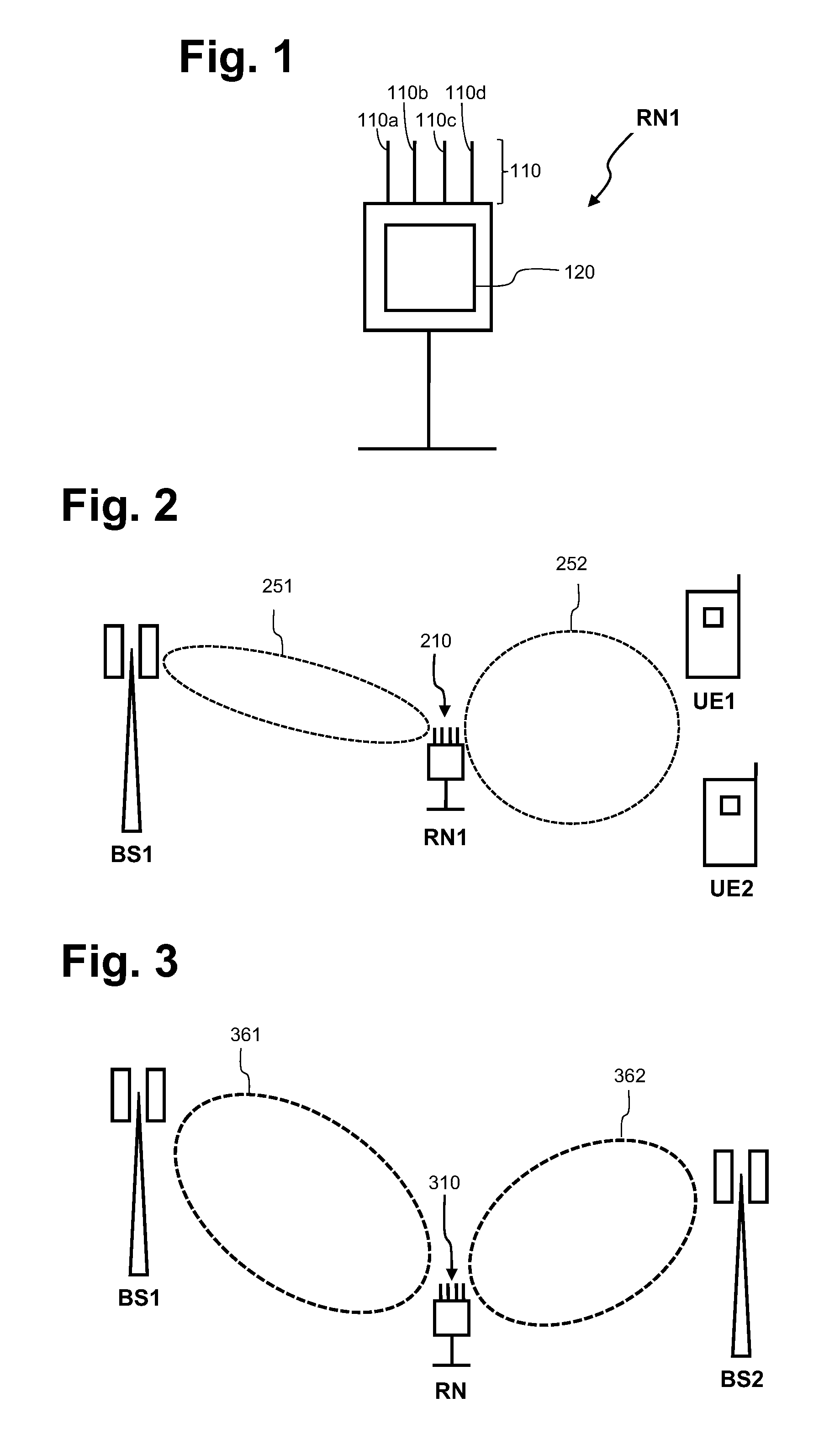
[0015]The described Relay Node (RN) is based on the idea that by using variable pattern antennas the RN could be able to optimize both (a) the backhaul respectively the link, which extends between the RN and its serving BS, and (b) the access link, which extends between the RN and UE(s) served by the RN. Thereby, the coverage of an intended service area can be significantly increased.
[0046]Each spatial characteristic antenna pattern may be selected for a short time such as for instance a few milliseconds. During this short time period the RN may radiate a predetermined test signal. Preferably, this test signal will be radiated with a maximum radio transmission power.

Problems solved by technology

Secondly, they have to provide cellular coverage to UEs, which are located in those areas where the donor BS cannot provide sufficient service level.
However, this may not be optimal from the indoor coverage point of view.
Generally speaking, known RNs do not ensure that the links to UEs can also have a high quality and this impacts the overall performance of the telecommunication network.
A low quality link between a UE and a RN can lead to increase the retransmission of data or to a possible request for handover, both of which will consume radio resources and increase the amount of signaling.

Method used


Image

  • Relay node operable with different spatial characteristic antenna patterns
  • Relay node operable with different spatial characteristic antenna patterns

Examples


Embodiment Construction

[0052]The illustration in the drawing is schematically. It is noted that in different figures, similar or identical elements are provided with the same reference signs or with reference signs, which are different from the corresponding reference signs only within the first digit.

[0053]FIG. 1 schematically shows a relay node RN1 which is adapted to operate with different spatial characteristic antenna patterns. The relay node RN1 comprises an antenna 110 with four antenna elements 110a, 110b, 110c and 110d. The relay node RN1 further comprises a transceiver unit 120, which is adapted to control the antenna elements 110a-d in such a manner that the antenna 110 exhibits a predefined spatial characteristic antenna pattern. According to the embodiment described here the antenna 110 is a flat panel multi beam antenna. This allows the relay node RN1 to be implemented by means of an all-in-one box relay node wherein a flat panel adjustable antenna is integrated into to the housing of the re...


PUM


Abstract

It is described a relay node for providing wireless access for a user equipment to a telecommunication network. The relay node includes an antenna, which is adapted to operate with different spatial characteristic antenna patterns, and a transceiver unit, which is coupled to the antenna and which is adapted to activate at least one of the different spatial characteristic antenna patterns. It is further described a corresponding method for providing wireless access for a user equipment to a telecommunication network via a relay node.

Description

FIELD OF INVENTION[0001]The present invention generally relates to the field of mobile telecommunication networks. In particular, the present invention relates to a relay node for a mobile telecommunication network. Further, the present invention relates to method for providing wireless access for a user equipment to a telecommunication network via a relay node such as the above mentioned relay node.ART BACKGROUND[0002]A cost efficient solution for improving the performance and in particular the spatial coverage of Long Term Evolution (LTE) and LTE-Advanced (LTE-A) telecommunication networks is the utilization of relay nodes (RN), which allows installations without having terrestrial broadband access or the need to install micro wave links. In a relay enhanced telecommunication network there are basically three different types of radio connections:[0003]A) A first type of radio connection is the connection between a base station (BS) and a user equipment (UE). This type of connectio...

Claims


Application Information

Patent Timeline
Patent Type & Authority Patents(United States)
IPC IPC(8): H04W72/04H04W88/04H04B7/02H04B7/04H04B7/06H04B7/08H04B7/155
CPCH04W72/048H04B7/1555H04B7/0695H04B7/155H04W88/04H04B7/0413H04B7/024H04B7/063H04B7/088H04W72/51
Inventor WAZ-AMBROZEWICZ, ANDRZEJPAKULSKI, MACIEJ
Owner WSOU INVESTMENTS LLC
Learn More