Fuel cell system having a fluid flow distribution feature

a technology of fluid flow and fuel cell system, which is applied in the direction of combustion-air/fuel-air treatment, ratio control, trickle cooler, etc., can solve the problems of unstable performance uneven relative humidity distribution across the outlet of the dry plate, and high ohmic voltage loss, so as to reduce the variation of the relative humidity distribution, the cost and complexity of the fuel cell system

Active Publication Date: 2015-05-12
GM GLOBAL TECH OPERATIONS LLC
View PDF11 Cites 9 Cited by
  • Summary
  • Abstract
  • Description
  • Claims
  • Application Information

AI Technical Summary

Benefits of technology

[0013]In concordance and agreement with the present invention, a fuel cell system including a fluid flow distribution feature, which minimizes a variation of the relative humidity distribution across the outlets of the flow channels of the dry plate of the WVT unit, as well as a cost and a complexity of the fuel cell system.

Problems solved by technology

For example, lower water content of the membrane leads to a higher proton conduction resistance, thus resulting in a higher ohmic voltage loss.
The uniform spacing of the flow channels of the plates results in uneven relative humidity distribution across outlets of the dry plate.
Liquid water in the fuel cell stack decreases durability and can result in unstable performance of the fuel cell system.
Typically, a liquid water separator is employed to militate against the liquid water from entering the fuel cell stack, adding cost and complexity to the fuel cell system.
However, an effectiveness of the liquid water separator may be less than optimal, permitting a portion of the liquid water to enter the fuel cell stack.

Method used


Image

  • Fuel cell system having a fluid flow distribution feature
  • Fuel cell system having a fluid flow distribution feature
  • Fuel cell system having a fluid flow distribution feature

Examples


Embodiment Construction

[0032]The following detailed description and appended drawings describe and illustrate various exemplary embodiments of the invention. The description and drawings serve to enable one skilled in the art to make and use the invention, and are not intended to limit the scope of the invention in any manner.

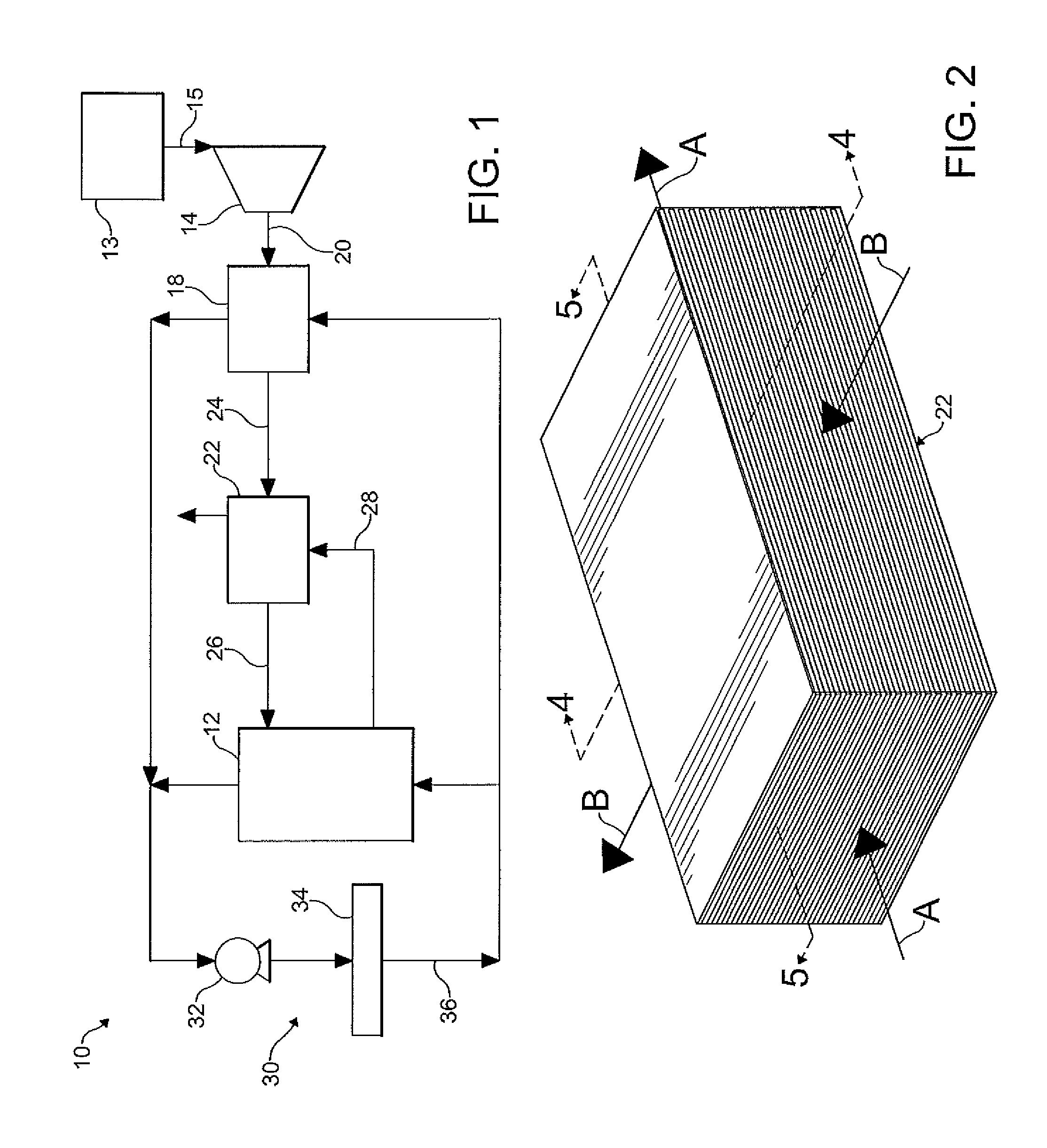
[0033]FIG. 1 schematically illustrates a fuel cell system 10 according to an embodiment of the present invention. The fuel cell system 10 includes a fuel cell stack 12 having a cathode side and an anode side. A cathode supply fluid stream, depending on a load requirement of the fuel cell stack 12, is supplied from a fluid source 13 to a compressor 14 through a conduit 15. Within the compressor 14, the cathode supply fluid stream is compressed. As shown, the compressor 14 is fluidly connected to a charge air cooler (CAC) 18 through a conduit 20. The CAC 18 cools the cathode supply fluid stream that has been heated as a result of the compression by the compressor 14. It is understood t...


PUM

PropertyMeasurementUnit
lengthaaaaaaaaaa
relative humidityaaaaaaaaaa
volumeaaaaaaaaaa

Abstract

A fuel cell system includes a water vapor transfer unit and a fluid flow distribution feature, the water vapor transfer unit including a first plate having a plurality of first flow channels for receiving a flow of a first fluid therein, and a second plate having a plurality of second flow channels for receiving a flow of a second fluid therein. The fluid flow distribution feature is configured to control at least one of a volume of flow of the first fluid through the first flow channels and a volume of flow of the second fluid through the second flow channels, wherein at least one of a flow distribution of the first fluid across the first plate and a flow distribution of the second fluid across the second plate is varied.

Description

FIELD OF THE INVENTION[0001]The invention relates to a fuel cell system and more particularly to a fuel cell system including a fluid flow distribution feature.BACKGROUND OF THE INVENTION[0002]Presently, fuel cell systems are being proposed for use as a power source in a wide variety of commercial and non-commercial applications. In particular, fuel cell systems are increasingly being used as a replacement for internal combustion engines in motor vehicles. Such a system is disclosed in commonly owned U.S. Pat. No. 7,459,227, hereby incorporated herein by reference in its entirety. Typically, the fuel cell system generates electricity which is then used to charge batteries or to provide power to an electric motor. Fuel cell systems may also be used as stationary electric power plants in buildings and residences, and as portable power in video cameras, computers, and the like.[0003]The fuel cell system is typically comprised of a plurality of fuel cells bundled together and arranged i...

Claims


Application Information

Patent Timeline
Patent Type & Authority Patents(United States)
IPC IPC(8): H01M12/00F22D1/28B01D47/00F28C1/00G05D11/00F02M25/10C10K1/00F02M25/00H01M8/10H01M8/04H01M2/36H01M8/00H01M8/06F16L53/00C10J1/00F16K49/00B01F3/04
CPCY02E60/50H01M8/04141H01M2008/1095Y10T137/2516Y10T137/2521Y10T137/265Y10T137/6497
Inventor ZHANG, YANFALTA, STEVEN R.BURCH, STEVEN D.SKALA, GLENN W.
Owner GM GLOBAL TECH OPERATIONS LLC
Why Eureka
Try Eureka