Imaging lens and imaging apparatus

a technology which is applied in the field of imaging lens and imaging apparatus, can solve the problems of increasing cost, difficult to produce low-cost lens systems, and increasing the requirements of imaging lens mounting on in-vehicle cameras, etc., and achieves the effects of low cost, wide angle of view, and small siz

Inactive Publication Date: 2015-05-12
TIANJIN OFILM OPTO ELECTRONICS CO LTD
View PDF37 Cites 11 Cited by
  • Summary
  • Abstract
  • Description
  • Claims
  • Application Information

AI Technical Summary

Benefits of technology

[0006]Meanwhile, requirements for an imaging lens to be mounted on an in-vehicle camera, a surveillance camera or the like have become tougher every year. Therefore, further reduction in the size and the cost of the imaging lens, a wider angle of view, and higher performance are needed.
[0007]Here, the lens systems disclosed in Patent Documents 1, 2, 4, 8, 9 and 11 are advantageous to chromatic aberrations and sensitivity, because cemented lenses are used. However, special cementing material and processing are required depending on usage conditions of the lens systems, and that increases the cost. In the lens system disclosed in Patent Document 3, a half angle of view is 40° or less, which is not sufficiently wide to achieve a wide angle of view to be addressed by the present invention. Further, the lens system disclosed in Patent Document 10 is an anamorphic lens. Therefore, it is impossible to produce the lens system at low cost.
[0008]In view of the foregoing circumstances, it is an object of the present invention to provide an imaging lens that can achieve small size, low cost, a wide angle of view, and high performance and an imaging apparatus including the imaging lens.

Problems solved by technology

Meanwhile, requirements for an imaging lens to be mounted on an in-vehicle camera, a surveillance camera or the like have become tougher every year.
However, special cementing material and processing are required depending on usage conditions of the lens systems, and that increases the cost.
Therefore, it is impossible to produce the lens system at low cost.

Method used


Image

  • Imaging lens and imaging apparatus
  • Imaging lens and imaging apparatus
  • Imaging lens and imaging apparatus

Examples


first embodiment

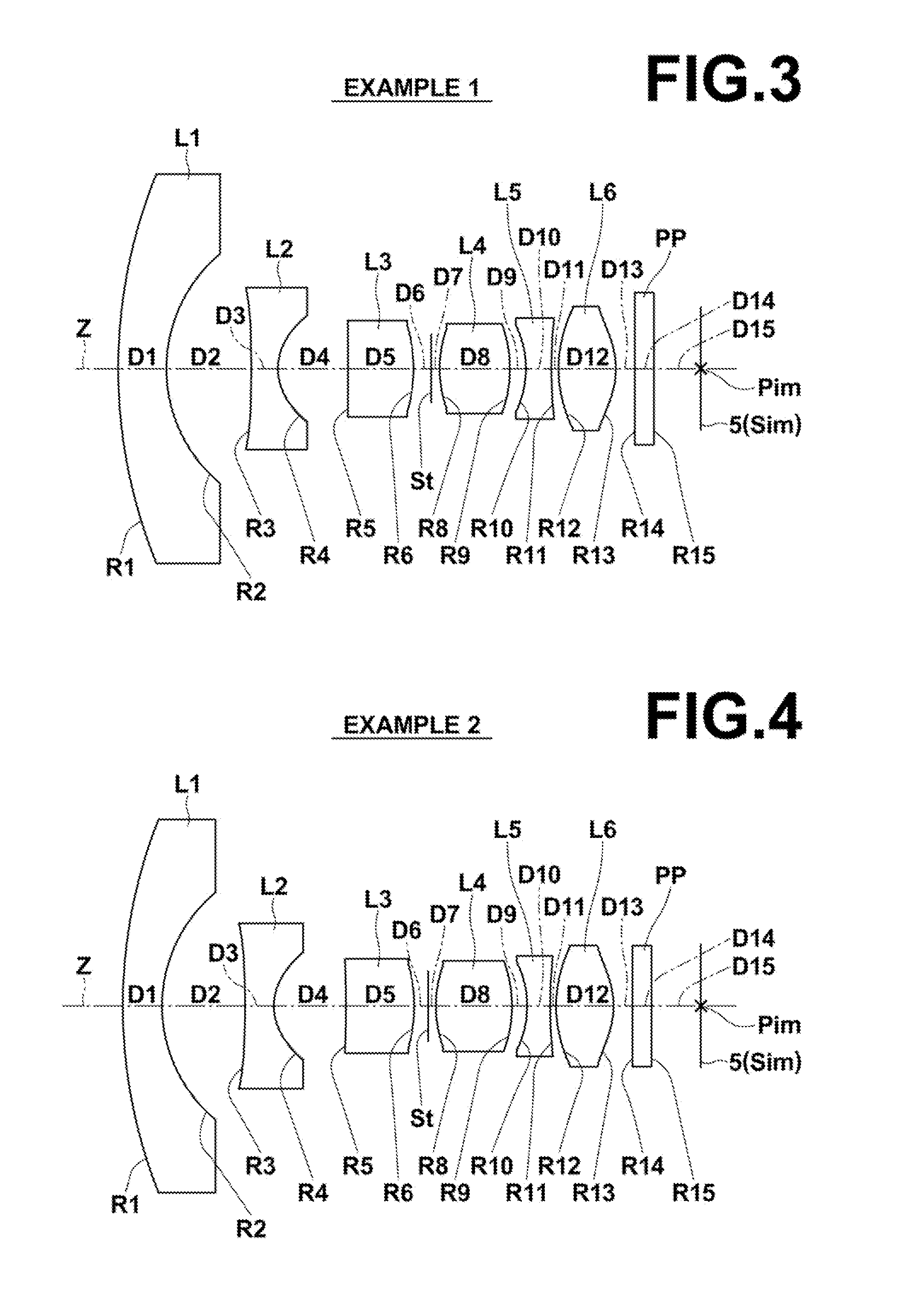
[0107]The imaging lens according to the present invention satisfies the following conditional formulas (1) and (6):

−0.61R8+R9) / (R8−R9)<0.44  (1); and

38.1<νd3+νd5<45.1  (6), where

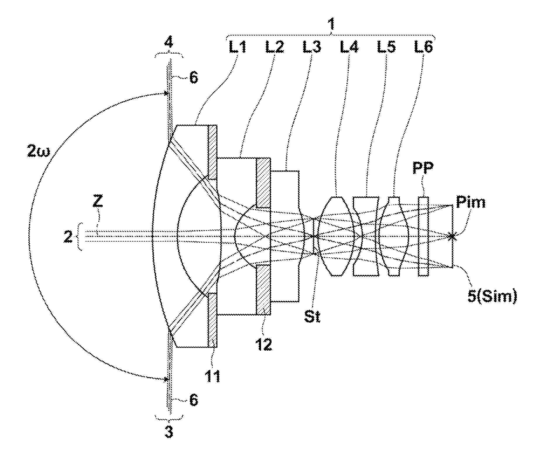
[0108]R8: a curvature radius of an object-side surface of fourth lens L4,

[0109]R9: a curvature radius of an image-side surface of fourth lens L4,

[0110]νd3: an Abbe number of the material of third lens L3 for d-line, and

[0111]νd5: an Abbe number of the material of fifth lens L5 for d-line.

[0112]When the upper limit and the lower limit of conditional formula (1) are satisfied, it is possible to make fourth lens L4 a biconvex lens, and to easily increase the refractive power of fourth lens L4. Therefore, it is possible to easily correct chromatic aberrations. When the lower limit of conditional formula (1) is satisfied, it is possible to easily prevent a curvature radius of the object-side surface from becoming small, and to easily correct curvature of field and a coma aberration. When the upper limit of con...

second embodiment

[0117]The imaging lens according to the present invention satisfies the following conditional formulas (1-1) and (12):

−0.11R8+R9) / (R8−R9)  (1-1); and

R9 / f<−2.9  (12), where

[0118]R8: a curvature radius of an object-side surface of fourth lens L4,

[0119]R9: a curvature radius of an image-side surface of fourth lens L4, and

[0120]f: a focal length of an entire system.

[0121]When the lower limit of conditional formula (1-1) is satisfied, it is possible to make fourth lend L4 a biconvex lens, and to easily increase the refractive power of fourth lens L4. Therefore, it is possible to easily correct chromatic aberrations. When the lower limit of conditional formula (1-1) is satisfied, it is possible to easily prevent a curvature radius of the object-side surface from becoming small, and to easily correct curvature of field and a coma aberration.

[0122]When the upper limit of conditional formula (12) is satisfied, it is possible to easily prevent the absolute value a curvature radius of the i...

third embodiment

[0126]The imaging lens according to the present invention satisfies the following conditional formulas (1-2) and (4):

−0.075R8+R9) / (R8−R9)<0.11  (1-2); and

−1.04R10+R11) / (R10−R11)<−0.34  (4), where

[0127]R8: a curvature radius of an object-side surface of fourth lens L4,

[0128]R9: a curvature radius of an image-side surface of fourth lens L4,

[0129]R10: a curvature radius of an object-side surface of fifth lens L5, and

[0130]R11: a curvature radius of an image-side surface of fifth lens L5.

[0131]When the upper limit and the lower limit of conditional formula (1-2) are satisfied, it is possible to make fourth lens L4 a biconvex lens, and to easily increase the refractive power of fourth lens L4. Therefore, it is possible to easily correct chromatic aberrations. When the lower limit of conditional formula (1-2) is satisfied, it is possible to easily prevent a curvature radius of the object-side surface from becoming small, and to easily correct curvature of field and a coma aberration. When...


PUM


Abstract

An imaging lens substantially consists of six lenses of a negative first lens, a negative second lens, a positive third lens, a positive fourth lens, a negative fifth lens and a positive sixth lens in this order from an object side. When a curvature radius of an object-side surface of the fourth lens is R8, and a curvature radius of an image-side surface of the fourth lens is R9, and an Abbe number of the material of the third lens for d-line is νd3, and an Abbe number of the material of the fifth lens for d-line is νd5, the following conditional formulas (1) and (6) are satisfied:−0.61<(R8+R9) / (R8−R9)<0.44  (1); and38.1<νd3+νd5<45.1  (6).

Description

BACKGROUND OF THE INVENTION[0001]1. Field of the Invention[0002]The present invention relates to an imaging lens and an imaging apparatus. In particular, the present invention relates to an imaging lens appropriate for use in an in-vehicle camera, a camera for a mobile terminal, a surveillance camera, or the like using an imaging device, such as a CCD (Charge Coupled Device) and a CMOS (Complementary Metal Oxide Semiconductor). Further, the present invention relates to an imaging apparatus including the imaging lens.[0003]2. Description of the Related Art[0004]In recent years, the size of an imaging device, such as a CCD and a CMOS, became very small, and the resolution of the imaging device became very high. Consequently, the size of the body of imaging equipment including such an imaging device became small. Therefore, reduction in the size of an imaging lens to be mounted on the imaging equipment is also needed in addition to excellent optical performance of the imaging lens. Mea...

Claims


Application Information

Patent Timeline
Patent Type & Authority Patents(United States)
IPC IPC(8): G02B13/04G02B3/02G02B9/62G02B13/00G02B13/06G02B13/18
CPCG02B13/06G02B13/0045G02B13/04G02B13/18G02B9/62
Inventor ASAMI, TAROKATSUMA, TOSHIAKIITO, TORUKONDO, MASATOOTOMO, RYOKO
Owner TIANJIN OFILM OPTO ELECTRONICS CO LTD
Why Eureka
Try Eureka