Telescoping landing leg system

a technology of landing leg and telescopic leg, which is applied in the field of aeronautic landing gear, can solve the problems of inclined or irregular surfaces that are unsuitable for landing such craft, airplanes, and birds that cannot take flight from almost any location, and achieve the effects of enlarge the scope of missions, increase versatility, and safe landing of helicopters

Active Publication Date: 2015-05-19
TLL ASSOC TRUSTEE FOR TELESCOPING LANDING LEG SYST CRT TRUST
View PDF36 Cites 40 Cited by
  • Summary
  • Abstract
  • Description
  • Claims
  • Application Information

AI Technical Summary

Benefits of technology

[0012]If the helicopter is just landing on a normal helipad or a flat surface, the telescoping landing leg system may be turned off and not used at all. With a telescoping landing leg system, the helicopter is given greater versatility to land on uneven terrain.
[0013]The telescoping landing leg system provides a mission-expanding capability to a helicopter. It enables a helicopter to land in previously unsuitable terrains and landscapes. It provides a capability to safely land a helicopter while holding the helicopter in a level attitude so the rotors stay level and inhibit dangers from tipping over, from rotor impact with the ground, or from rotor impact with nearby objects. The telescoping landing leg system opens up a whole new realm of possibilities for both military missions and search and rescue uses. The telescoping landing leg system enlarges the scope of missions to save lives and aid military or law enforcement agencies.
[0014]The telescoping landing leg system may be made in a lower-priced pilot-controlled manual version, whereby the helicopter pilot pushes buttons to extend out each telescoping landing leg.
[0015]The telescoping landing leg system makes a quantum technological leap to move us closer to that beautiful and wonderful ability that a bird has.
[0016]The telescoping landing leg system will save lives and provide uplifting benefit to all of mankind throughout the world.

Problems solved by technology

Inclined or irregular surfaces are unsuited for landing such craft because of the dangers associated with other than horizontal rotation of the craft's rotors.
An airplane, however, cannot match the ability of birds to take flight from almost any location and to land in almost any location.

Method used


Image

  • Telescoping landing leg system
  • Telescoping landing leg system
  • Telescoping landing leg system

Examples


Embodiment Construction

[0026]In the following description, reference is made to the accompanying drawings, which form a part hereof and which illustrate several embodiments of the present invention. The drawings and the preferred embodiments of the invention are presented with the understanding that the present invention is susceptible of embodiments in many different forms and, therefore, other embodiments may be utilized and structural, and operational changes may be made, without departing from the scope of the present invention.

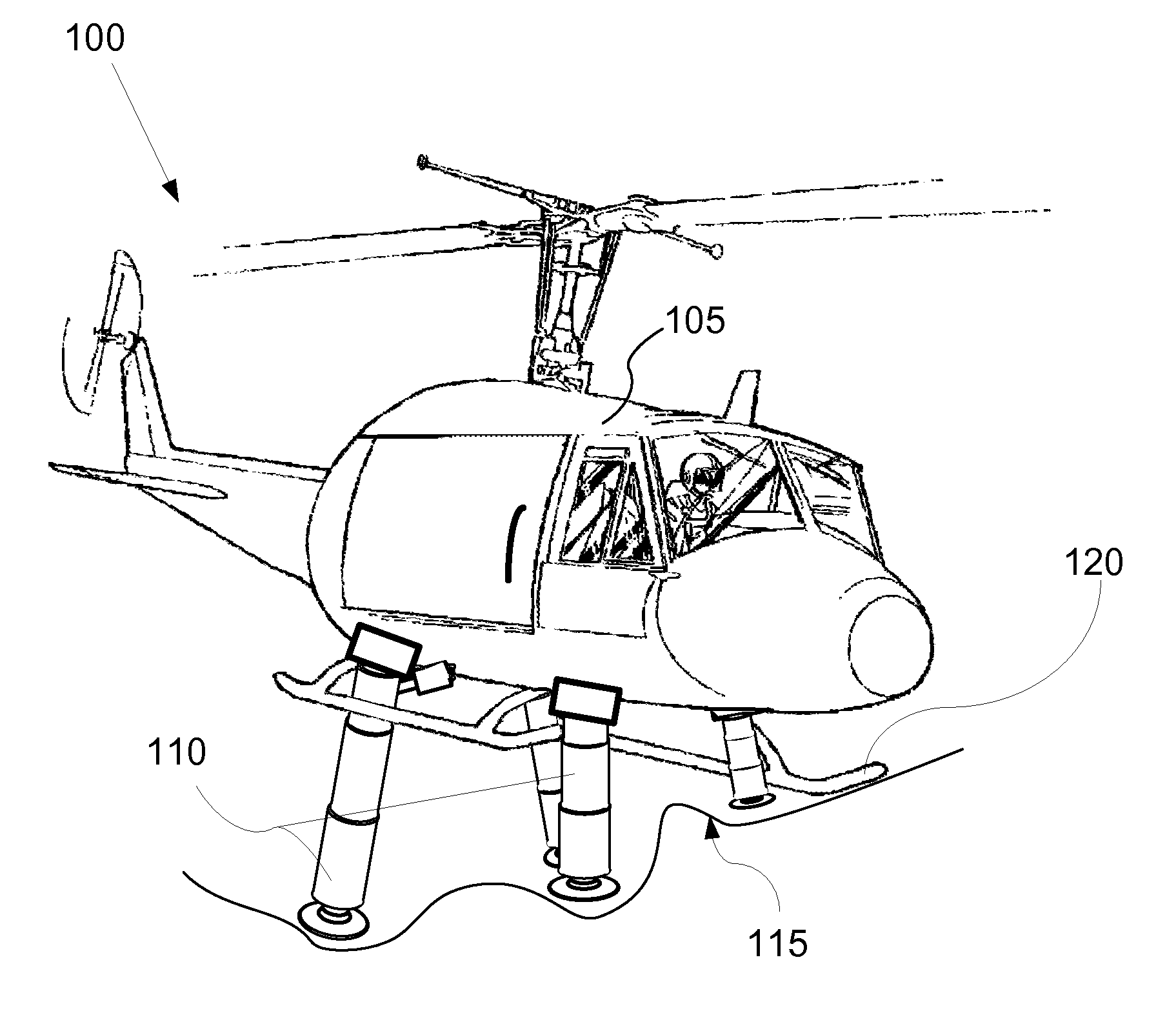
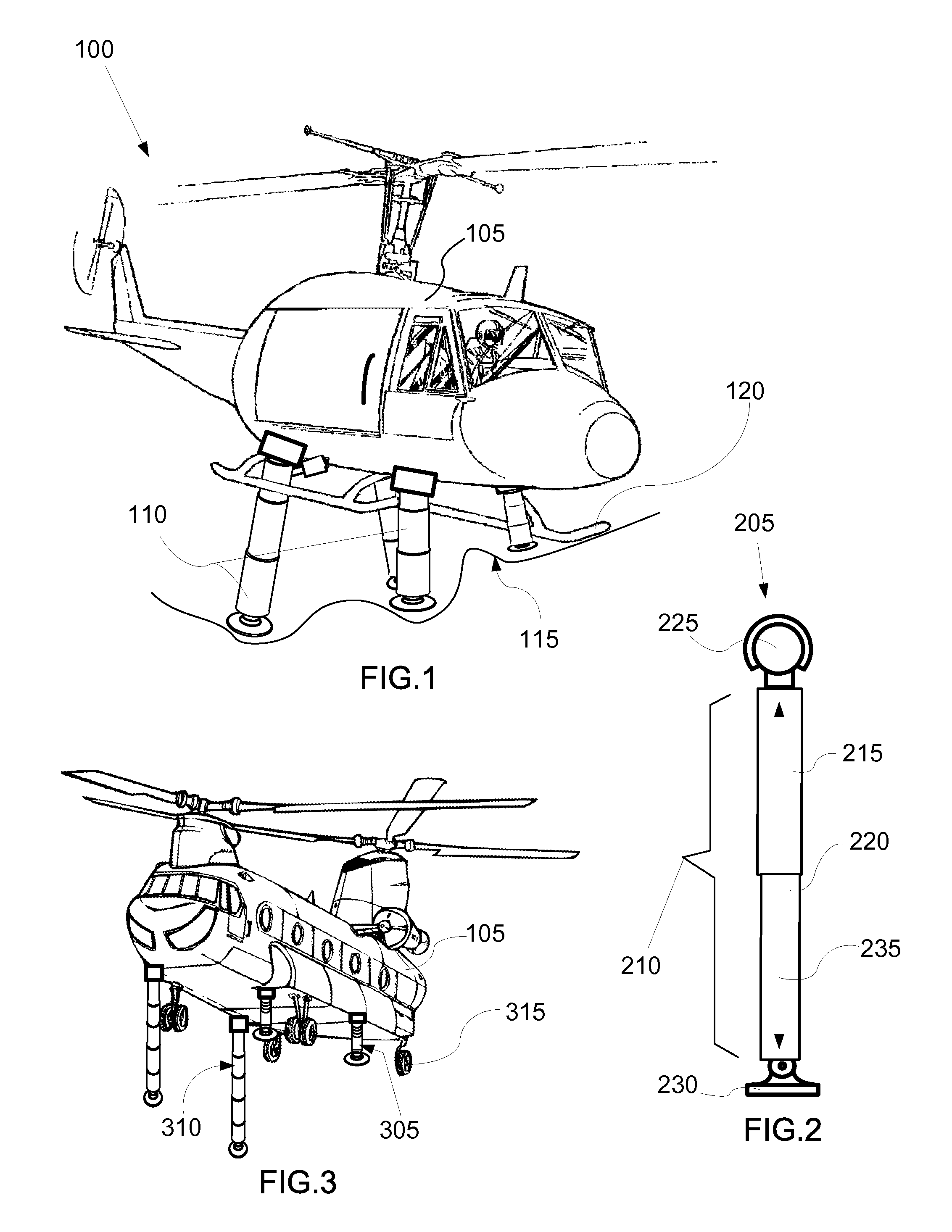
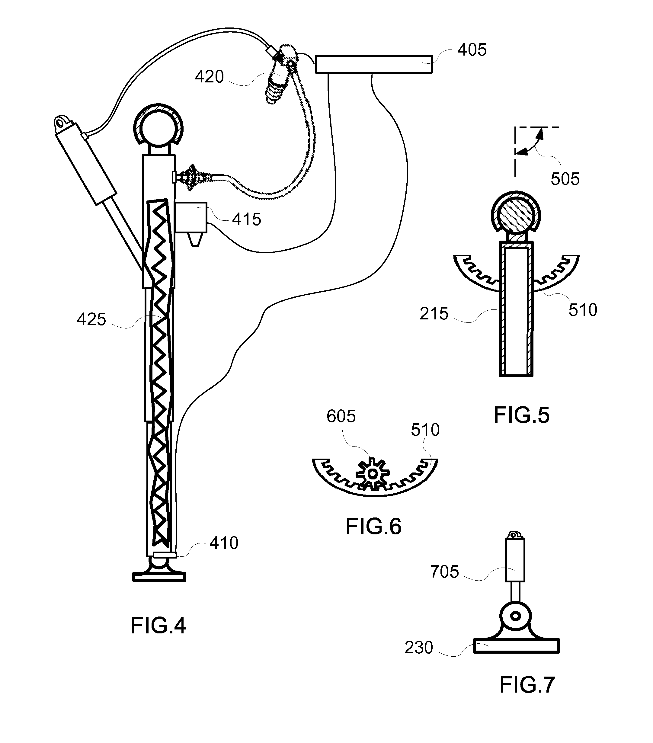
[0027]The telescoping landing leg system (100) includes an aerial vehicle (105), a plurality of legs (110) having nested sections (210) that telescope in and out during operation of the telescoping landing leg system (100), a central processing unit (405), and a rangefinder (415) for each leg. FIGS. 1 and 4 show these components. FIG. 1 is a perspective of an embodiment of the telescoping landing leg system (100).

[0028]The aerial vehicle (105) is any aircraft capable of vertica...


PUM


Abstract

A telescoping landing leg system includes an aerial vehicle capable of vertical takeoff and landing; and a plurality of legs. Each leg has at least two nested sections. A first section is fixed to the aerial vehicle and a second section slidably retained within the first section. The second section extends out of the first section by telescoping therefrom to engage the ground when the aerial vehicle is landing. A central processing unit may be used to control extension of any leg independently of any other leg in the plurality of legs. Sensors may be used to provide data to the central processing unit.

Description

TECHNICAL FIELD[0001]In the field of aeronautic, landing gear in the form of telescoping members that enable vertical takeoff and landing aerial vehicles to land on non-flat surfaces.BACKGROUND ART[0002]Helicopters and other vertical take-off and landing aircraft essentially require a horizontal and flat landing space. Inclined or irregular surfaces are unsuited for landing such craft because of the dangers associated with other than horizontal rotation of the craft's rotors. Thus, for safety of the aircraft and any persons on the ground, the landing gear of all such aircraft form a horizontal plane for landing on a flat landing pad or relatively flat ground.[0003]For many thousands of years, mankind has dreamed of being able to fly as he has watched the beauty and technological wonder of birds in flight. Since the days of Kitty Hawk and the Wright brothers, the airplane has given man the ability to take flight. An airplane, however, cannot match the ability of birds to take flight ...

Claims


Application Information

Patent Timeline
Patent Type & Authority Patents(United States)
IPC IPC(8): B64C25/32B64C25/10
CPCB64C25/10B64C25/32B64C2025/325B64C2025/008
Inventor CALVERT, S. MILL
Owner TLL ASSOC TRUSTEE FOR TELESCOPING LANDING LEG SYST CRT TRUST
Why Eureka
Try Eureka