Autofocusing method and device for a microscope

a technology of autofocusing and microscope, which is applied in the field of autofocusing method and autofocusing device for microscope, can solve the problems of difficult detection of laser dots, and inability to pass through the focal plane region too quickly, so as to reduce the spacing of markers and speed up the focusing speed. , the effect of speeding up the focusing driv

Active Publication Date: 2015-05-19
LEICA MICROSYSTEMS (SCHWEIZ) AG
View PDF10 Cites 5 Cited by
  • Summary
  • Abstract
  • Description
  • Claims
  • Application Information

AI Technical Summary

Benefits of technology

[0016]According to the present invention, the speed at which the focus drive displaces the working plane into the focal plane is adjusted, for autofocusing, as a function of the spacing of the markers located on the object. To simplify the explanation it will be assumed hereinafter, with no limitation of generality, that the predefined spacing dF of the markers at which the working plane is located in the focal plane is intended to equal zero, i.e. that when the working plane is optimally focused, the markers merge with one another or become coincident.
[0017]The speed of the focus drive (also referred to as “focusing speed”) is to be controlled proportionally to the spacing of the markers. In other words, the smaller the spacing of the markers, the slower the focusing speed (speed of the focus drive) that is selected. Conversely, the farther apart the markers are from one another, the greater the speed of the focus drive (focusing speed) that is selected. For further explanation it will be assumed, with no limitation of generality, that exactly two markers are generated on the object. Upon focusing, the two markers move toward one another, and merge when the focal plane is reached. In a special case discussed later on, two markers are used, one of which is a so-called target marker that is generated by a corresponding beam path along the optical axis. The target marker remains immobile during the focusing operation, while a further marker moves toward said target marker.
[0018]Because the speed of the focus drive is adjusted proportionally to the marker spacing, the focusing speed is greater in a context of large spacings from the focus, so that the user no longer perceives the corresponding focus adjustment as time-consuming. Conversely, the focusing speed is lower for small spacings from the focus, so that, in particular at high microscope magnifications at which the markers quickly move toward one another, a corresponding speed “throttling” occurs. As will be further explained separately below, the microscope magnification can also be incorporated into the focusing speed control system as a further parameter.
[0019]It has proven to be advantageous if the proportional correlation between the focusing drive speed and the marker spacing can be represented by a polynomial function or an exponential function. A quadratic function or an exponential function is particularly advantageous.
[0020]A polynomial function can be presented in the following form:
where k0 and k1 are coefficients of the exponential function.
where v designates the focusing speed and d the marker spacing. k0 to kx designate the coefficients of the x-th-order polynomial function. In practice, a fourth-order function is sufficient; a quadratic function (second-order polynomial function) is advantageous.
where k0 and k1 are coefficients of the exponential function.
[0022]To generate the markers on the object, corresponding autofocus beam paths are coupled into the beam path of the microscope. For generation of the corresponding autofocus beam paths, it is advantageous to use one or more point light sources. A “point light source” is to be understood as point-like light sources, such as LEDs or laser beam sources, that exhibit, in particular, a high parallelity of radiation. It is particularly preferred to use a laser diode. The radiation of the laser diode can serve as an autofocus beam path for generating a marker on the object. For this, the autofocus beam path is coupled via beam splitters into the beam path of the microscope. Alternatively, however, two (or more) point light sources can also be arranged directly in the beam path of the microscope. It is advantageous in this context if the two point light sources are arranged at the outermost edge of the beam path of the microscope, in particular outside the observation pupil of the objective.
[0023]Modern microscopes, in particular surgical microscopes, comprise a zoom system that is arranged after the microscope objective. Stereomicroscopes comprise a separate zoom system for each observation channel, which effect identical magnification in the two channels. With such microscopes, it is advantageous to perform the incoupling of the autofocus beam paths via beam splitters between the objective and the zoom system, or the zoom systems in the case of a stereomicroscope. Analogously, in the case of point light sources that are arranged in the beam path of the microscope, said sources are arranged between the objective and the zoom system(s). The consequence of such an arrangement is that the diameter of the markers (laser spots) on the object remains the same regardless of the zoom magnification that is set, while the image of the markers is correspondingly magnified if the detector is, for its part, arranged behind the zoom system.
[0024]A further essential advantage of arranging the point light sources between the objective and zoom system(s), or of incoupling the autofocus beam paths between the objective and zoom system(s), is that the two autofocus beam paths can then be incoupled outside the active cross section (hereinafter “observation pupil”). This configuration will be discussed again separately below in the context of the exemplifying embodiments.
[0025]In general, the zoom systems used are afocal zoom systems that are arranged behind an objective that images to infinity. In such cases, the autofocus beam paths extend in the beam path of the microscope parallel to the optical axis of the microscope. Once again, incoupling or generation of the autofocus beam paths (laser beam paths, when a laser diode is used) outside the observation pupil is advantageous. When a different type of objective is used, the autofocus beam paths (laser beams, when a laser diode is used) are to be arranged correspondingly in convergent or divergent fashion if the markers are to merge in the focal plane. In principle, exact alignment of the autofocus beam paths relative to the optical axis is not of essential importance provided the markers that are generated have, in the focal plane, a predefined unique or unambiguous spacing dF from one another; that spacing can also be not equal to zero.
[0026]Zoom systems usually used in surgical microscopy have a zoom factor of 6 (maximum to minimum zoom magnification); the objectives usually used are multifocus objectives or so-called vario objectives, having adjustable focal lengths typically from 20 cm to 50 cm.
[0027]The autofocus beam paths extending through the microscope objective generate corresponding markers on the object. The radiation of the markers reflected from the object, hereinafter referred to for the sake of simplicity as “autofocus beam paths reflected from the object,” extends through the observation beam path or paths of the microscope. It is useful to couple the image of the markers out of the observation beam path of the microscope by means of a corresponding beam splitter. When a zoom system is present, it is advantageous to perform this outcoupling behind the zoom system (as viewed from the objective). The beam splitter guides the outcoupled beam path onto a detector (camera), on whose light-sensitive sensor surface the marker image is then produced. In the case of a stereomicroscope it is useful to perform outcoupling of the reflected autofocus beam paths only out of one of the two observation beam paths of the stereomicroscope, since imaging of a monoscopic marker image is entirely sufficient for determining the spacing of the markers.
[0028]Especially in the context of manual autofocusing, for example by a surgeon as operator of a surgical microscope, it is useful to generate the markers using different wavelengths of the corresponding autofocus beam paths, which wavelengths should then derive from the visible wavelength region. This also makes it easy to detect passage through the focal plane, since the markers then “switch” colors. The focusing direction is thus easy to monitor.
[0029]In the context of automatic autofocusing, conversely, it is useful to use markers that are not visible to the human eye, i.e. in particular from the infrared wavelength region. Care must of course be taken that the beam splitters used to incouple and outcouple the autofocus beam paths, and the detector for acquiring the marker image, are designed for the autofocus beam path wavelengths that are used.
[0030]In accordance with an embodiment already indicated above, a target marker generated on the object by a target beam path extending along the optical axis of the microscope can be used. An advantage of such a target marker is that the focus destination, i.e. that region around the target marker which is being focused on, is indicated. This is advantageous in particular with three-dimensional object structures having elevations and depressions. It is advantageous in this connection to use a visible target marker, so that a surgeon or other operator of the microscope can see which object region is being focused on. The target marker can be used in addition to the (at least) two markers generated on the object that are used for autofocusing as described above.
[0031]Alternatively, the target marker can also replace one of the markers that are used for autofocusing as a function of the marker spacing. In this case one marker approaches the stationary target marker, and the two markers merge with one another when the focal plane is reached (with no limitation of generality).
[0032]For use of a manual autofocusing system, it is particularly advantageous to use visible autofocus beams to generate visible markers, in which context different wavelengths are used (e.g. a red and a green marker). In this case the operator of the microscope simultaneously sees the object region that is being focused on, so that a target marker is not absolutely necessary. In the case of automatic autofocusing, on the other hand, the use of invisible markers (in particular from the infrared wavelength region) is particularly preferred. The autofocus markers then do not influence optical investigation of the object region by the microscope operator. It is useful in this case to use a visible target marker, however, so that the microscope operator (surgeon) can detect the object region that is being focused on and can actively modify it as applicable.
[0033]The statements made above regarding markers also apply to the generation of a target marker, in particular with regard to incoupling of the corresponding target beam path and to the arrangement and use of point light sources for generating the target beam path.
[0034]As already indicated earlier, it is useful to adjust the speed of the focus drive additionally as a function of the microscope magnification. At a high microscope magnification, the speed at which the markers approach one another as the working plane approaches the focal plane is very much greater than at a lower microscope magnification. For a predefined distance between the working plane and the focal plane, however, the spacing of two marker points on the sensor / detector is also greater at a high microscope magnification than at a low microscope magnification. If the distance between the focal plane and the current working plane is the same in both cases, however, the focus speed should also have the same value. It is therefore useful to make the proportional correlation between the focus drive and marker spacing additionally dependent on the parameter of microscope magnification.
[0035]For this advantageous embodiment, the value of the microscope magnification must be delivered to the autofocus evaluation and control unit. Because the modifiable microscope magnification is determined chiefly by the modifiable zoom magnification, it is sufficient to deliver that zoom magnification Γ to the evaluation and control unit. The value of Γ is usually between 0.4 and 2.4.
[0036]It is advantageous to account for the microscope magnification by modifying the ascertained marker spacing. With no limitation of generality, only the zoom magnification will be considered below. The following modification of the marker spacing is particularly preferred:
At high zoom magnification (Γ=2.4), the large spacing of markers d is correspondingly reduced to d′. At a low zoom magnification (Γ=0.4), however, the small marker spacing d is increased to d′. The influence of zoom magnification on focusing speed can consequently be eliminated by this modification of the marker spacing. All that is necessary is to replace d with d′ in the equations described above.
[0037]With the present configuration for autofocusing, it is possible to ascertain the microscope magnification from the rate of change in the marker spacing at a constant focus drive speed. Specifically: the higher the microscope magnification, the greater the speed at which the markers on the object will move toward one another as the focal plane is approached, if the focus drive speed remains set to a constant value. For example, the system can be calibrated for known microscope magnifications in terms of the rate of change in the marker spacing at a constant focus drive speed, and upon subsequent operation the particular microscope magnification that is set can be ascertained from that calibration curve. Alternatively, in present-day modern microscopes the microscope magnification or zoom magnification can as a general rule be picked off or tapped as an electronic signal.
[0038]The invention further relates to an autofocus device for carrying out the method according to the present invention discussed in detail above. All statements in conjunction with the method and its embodiments are valid similarly for the autofocus device according to the present invention, without requiring separate explanations for that purpose. The description hereinafter of the autofocus device and its embodiments will therefore be limited to the apparatus elements necessary therefor.
[0039]The autofocus device according to the present invention comprises a detector for acquiring a microscopic image of the markers generated on the object; also provided is an evaluation unit that determines the spacing of the markers. As a function of the determined marker distance and optionally of further microscope parameters, such as in particular the microscope magnification or zoom magnification, the speed of the focus drive, i.e. the speed at which the working plane is displaced into the focal plane, is adjusted by means of a control unit. Be it noted in this connection that the focus drive can be operatively connected to a corresponding multifocus or vario objective whose focal length is modifiable within a predefined range. Alternatively or additionally, (at least) the microscope objective can be shifted in the direction of the optical axis in order to adjust the focus. Again alternatively or additionally, the microscope stage on which the object to be investigated is positioned can be shifted along the optical axis for focusing purposes. The focusing drive can consequently act on one or more of the components described, the “speed of the focus drive” always being intended to mean the speed at which the working plane in the object is displaced into the focal plane.
[0040]A particularly suitable configuration of an autofocus device for autofocusing in a microscope can be described as follows: On the side of the microscope objective facing away from the object, two point light sources are arranged in front of the zoom system arranged downstream from the objective. It is assumed that the objective images at infinity. The point light sources generate autofocus beam paths extending parallel to the optical axis. The point light sources are, in particular, arranged outside the observation pupil. If the working plane of the object is located in the focal plane, the markers generated on the object by the autofocus beam path merge or become coincident. A beam splitter, which couples the image of the markers out of the observation beam path of the microscope and delivers it to a detector (camera), is arranged behind the zoom system as viewed from the object. In the case of a stereomicroscope having two zoom systems for generating two observation beam paths, it is sufficient if the beam splitter is arranged behind one of the two zoom systems, i.e. in one of the two observation beam paths. The detector is operatively connected to an evaluation unit. A determination of the spacing of the markers in the marker image occurs in this evaluation unit. A corresponding control signal for a focus drive speed is associated with the marker spacing. A corresponding control unit conveys this signal to the focus drive. The focus drive is in turn connected to the corresponding microscope component that is responsible for focusing the microscope. This can be one or more of the following components: multifocus or vario objective, z displacement of the objective, and z displacement only of the microscope stage (“z displacement” meaning a displacement in the direction of the optical axis). When a multifocus objective is used, it may be useful to provide, in addition to focusing with the multifocus objective, a focusing action by means of a shift of the objective or of the microscope stage, if the defocusing lies outside the range that can be covered with the multifocus objective.
[0041]It is understood that the features recited above and those yet to be explained below are usable not only in the particular combination indicated, but also in other combinations or in isolation, without departing from the scope of the present invention.

Problems solved by technology

If there is a large deviation between the optimum focal plane and the object plane, the procedure of bringing the object plane closer to the optimum focal plane is usually perceived by the user to be too time-consuming.
At high magnifications, conversely, the fixed focusing speed can cause the region of the focal plane to be passed through too quickly.
Because of the shallow depth of field at high magnifications, detection of the merger of the laser dots, in particular by a user, is often possible only with difficulty.

Method used


Image

  • Autofocusing method and device for a microscope
  • Autofocusing method and device for a microscope
  • Autofocusing method and device for a microscope

Examples


Embodiment Construction

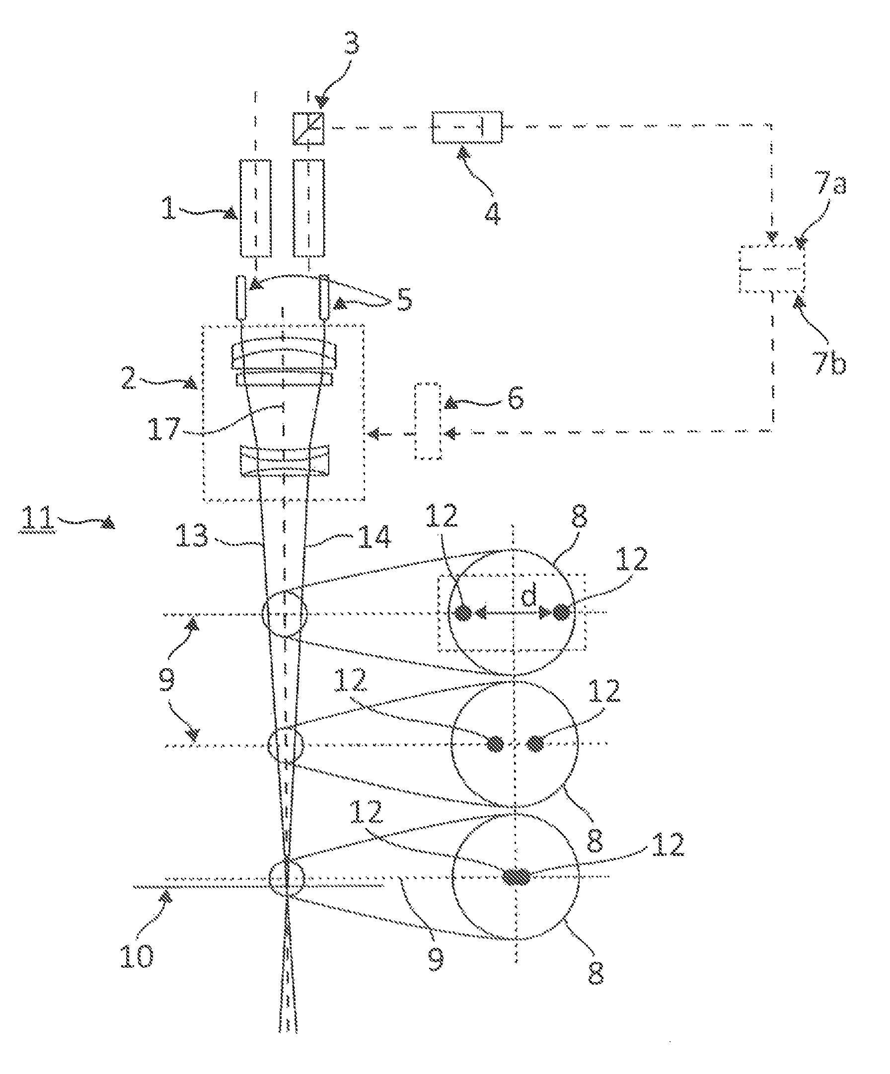
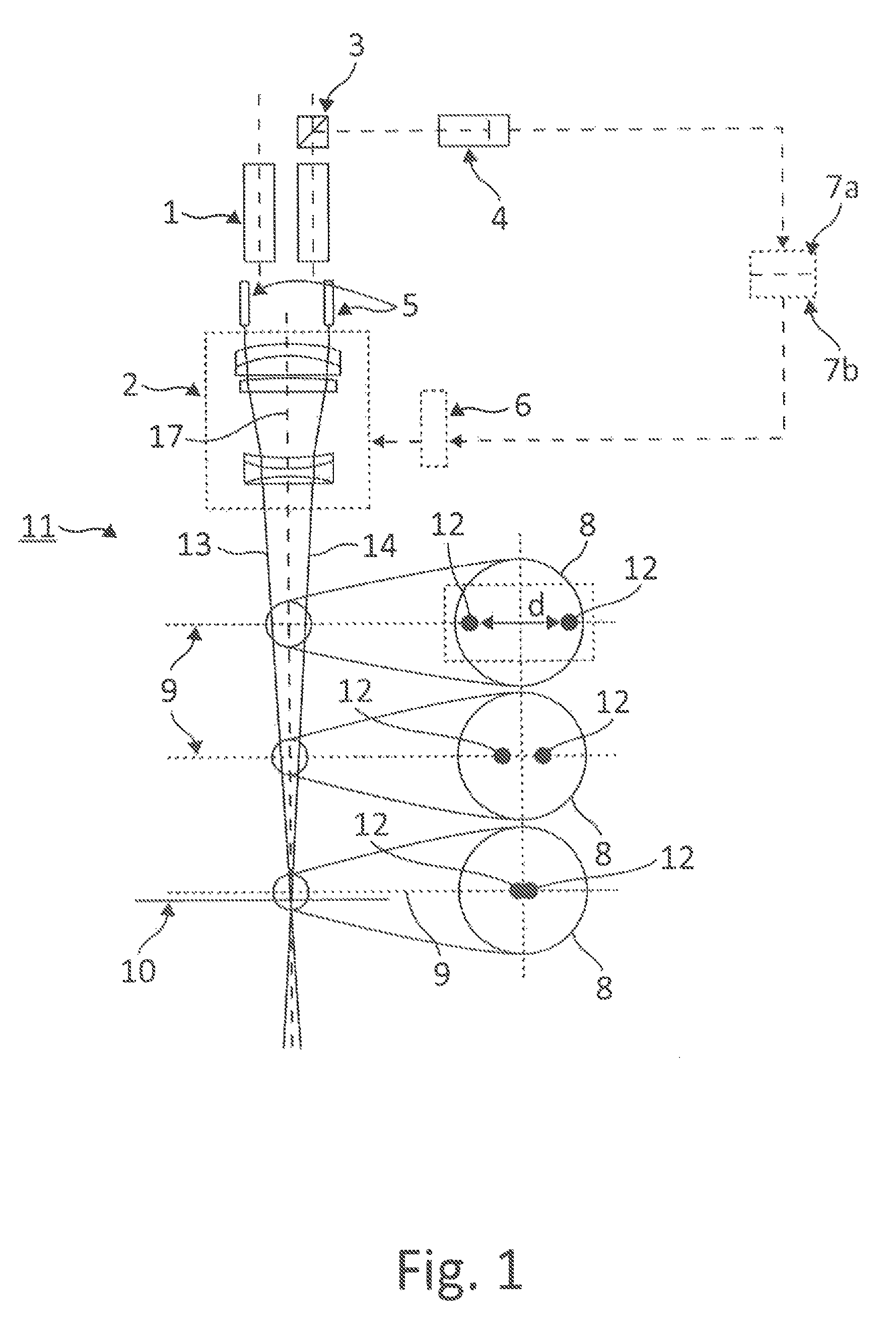
[0046]FIG. 1 schematically shows a particularly preferred embodiment of an autofocus device for autofocusing in a microscope 11. Only the most essential components of the microscope (here a stereomicroscope) are depicted, to the extent necessary for explaining the present invention. In this embodiment, the stereomicroscope 11 comprises a multifocus objective 2 as well as a zoom system 1 made up of two zoom channels. Further components of the stereomicroscope, such as the binocular tube, are not depicted here. For the sake of simplicity, it will be assumed that the focusing of microscope 11 is performed exclusively by means of multifocus objective 2. Shifts of objective 2 and / or of the microscope stage (not depicted) for focusing purposes are accordingly not considered in the present case.

[0047]The autofocus device is made up substantially of a detector 4, an evaluation unit 7a and a control unit 7b which are combined into one common unit, and focus drive 6 that controls multifocus o...


PUM


Abstract

A method and device for autofocusing in a microscope (11), wherein two preferably spot-shaped, markers (12) are generated on an object, the spacing (d) of the markers representing an indication of the defocusing of a working plane (9) in the object from the focal plane (10) of the microscope (11). A focus drive (6) displaces the working plane (9) into the focal plane (10) as a function of the marker spacing (d). In order to allow rapid and exact focusing to be performed, a detector (4) acquires an image of the markers (12) generated on the object, an evaluation unit (7a) determines the spacing of the markers (12), and a control unit (7b) adjusts, as a function of the determined marker spacing (d), the speed of the focus drive (6) at which the working plane (9) is displaced into the focal plane (10).

Description

CROSS REFERENCE TO RELATED APPLICATIONS[0001]This application claims priority of German patent application number 10 2011 082 756.0 filed Sep. 15, 2011, the entire disclosure of which is incorporated by reference herein.FIELD OF THE INVENTION[0002]The present invention relates to an autofocusing method and an autofocusing device for a microscope, in particular a surgical microscope, of the type wherein at least two markers are generated on an object and the spacing between the markers indicates the defocusing of a working plane in the object from the focal plane of the microscope.BACKGROUND OF THE INVENTION[0003]Known autofocus devices comprise an autofocusing optic for generating an autofocus beam path that generates an autofocus pattern on the object, the autofocus beam path usually being guided onto the object by means of a deflection element. An autofocus device of this kind furthermore comprises an autofocus evaluation unit to which a detector beam path is delivered by means of...

Claims


Application Information

Patent Timeline
Patent Type & Authority Patents(United States)
IPC IPC(8): H04N7/18G02B21/02G02B7/28G02B21/00
CPCG02B21/025G02B7/282G02B21/0012H04N7/18G02B21/245
Inventor KUSTER, MANFRED
Owner LEICA MICROSYSTEMS (SCHWEIZ) AG
Why Eureka
Try Eureka