Capacitive data transfer in an electronic lock and key assembly

a technology of electronic locks and key assemblies, applied in the field of electronic locks, can solve the problems of battery requiring constant replacement or recharging, the inability of locks of this type to use alternating current (ac) power supplies, and the inability to use power supplies to function properly

Active Publication Date: 2015-05-26
KNOX ASSOC INC DBA KNOX
View PDF195 Cites 22 Cited by
  • Summary
  • Abstract
  • Description
  • Claims
  • Application Information

AI Technical Summary

Problems solved by technology

One drawback of certain electronic locks is that they use a power supply to function properly.
Typically, locks of this type are unable to use alternating current (AC) power supplies, such as from wall outlets, due to the inherit lack of security and mobility of such power supplies.
Batteries may be used instead, but batteries may require constant replacement or recharging.
If a battery dies, a lock might fail to function and thereby create a significant security risk.
Electromagnets may also be employed, but the bulk of such devices in some instances limit the potential use of electronic locks to larger-scale applications.
However, electrical contacts suffer from the drawback of being susceptible to corrosion, potentially leading to failure of either the key or the lock.
Moreover, if separate inductors are used instead to transfer both power and data, magnetic interference between the inductors can corrupt the data and disrupt power flow to the lock.

Method used


Image

  • Capacitive data transfer in an electronic lock and key assembly
  • Capacitive data transfer in an electronic lock and key assembly
  • Capacitive data transfer in an electronic lock and key assembly

Examples


Embodiment Construction

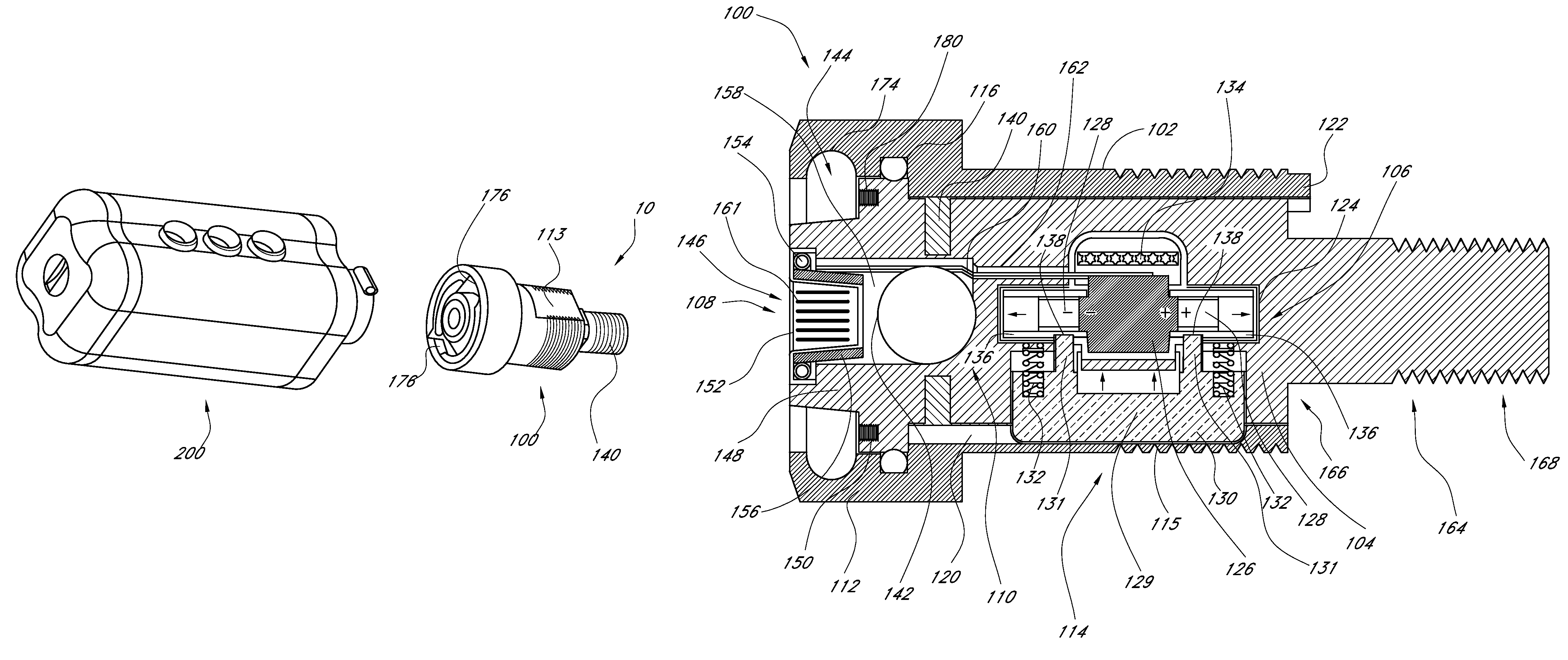
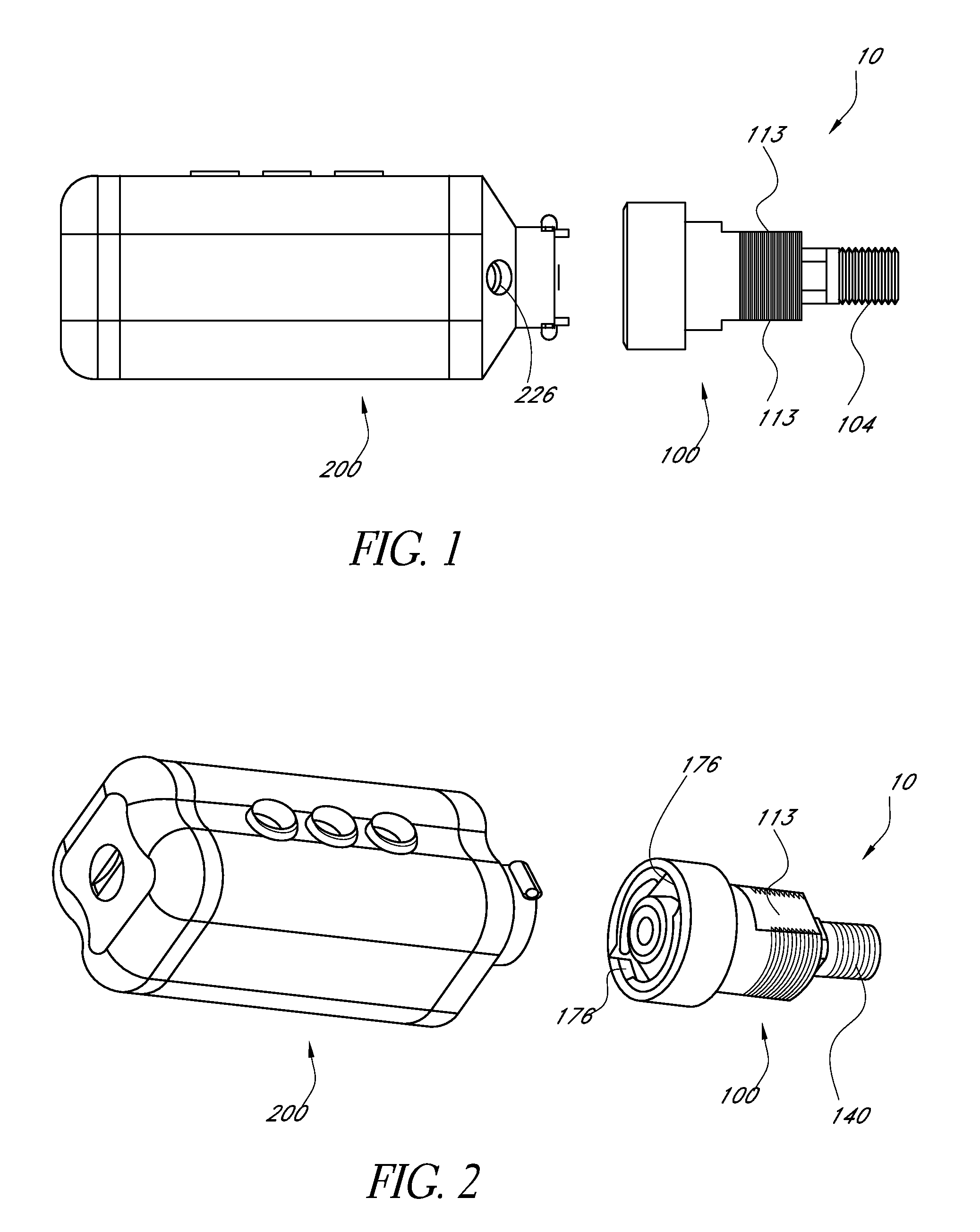
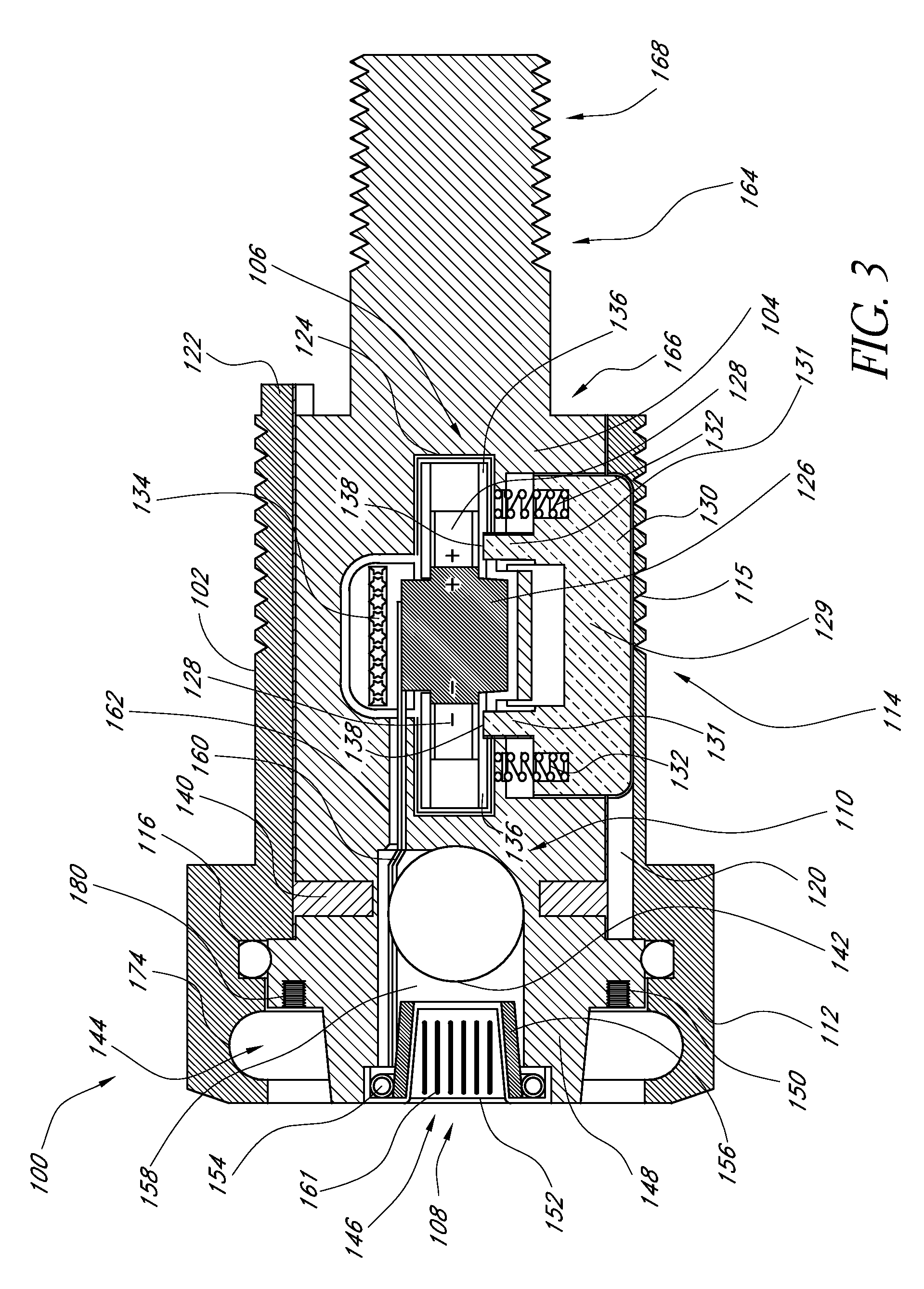
[0062]In the description below certain relative terms such as top, bottom, left, right, front and back are used to describe the relationship between certain components or features of the illustrated embodiments. Such relative terms are provided as a matter of convenience in describing the illustrated embodiments and are not intended to limit the scope of the technology discussed below.

[0063]Electronic key and lock assemblies can advantageously incorporate contactless power and / or data transfer as a technique of electrical communication between key and lock components. In addition to inductive power and / or data transfer using transmitters and receivers fitted with electrical coils, an alternative approach utilizes a capacitive, rather than inductive, interface as a mechanism of delivering an electrical signal. Use of a capacitive interface may provide certain advantages over an inductive interface. For example, with a capacitor, electromagnetic fields may be generally confined betwee...


PUM


Abstract

An electronic key may include a partial capacitor comprising a capacitive metal plate in communication with a processor. The capacitive metal plate of the partial capacitor is configured to form a capacitor with a corresponding capacitive metal plate of a lock when brought into proximity with the metal plate of the lock. Data may be transferred from the key to the lock using a capacitor formed by combining the two metal plates, wherein a common ground is established between the metal plate of the key and the metal plate of the lock through a parasitic capacitance present between the key and lock circuitry.

Description

BACKGROUNDDescription of the Related Art[0001]Electronic locks have a number of advantages over normal mechanical locks. For example, electronic locks may be encrypted so that only a key carrying the correct code will operate the lock. In addition, an electronic lock may contain a microprocessor so that, for example, a record can be kept of who has operated the lock during a certain time period or so that the lock is only operable at certain times. An electronic lock may also have the advantage that, if a key is lost, the lock may be reprogrammed to prevent the risk of a security breach and to avoid the expense associated with replacement of the entire lock.[0002]One drawback of certain electronic locks is that they use a power supply to function properly. Typically, locks of this type are unable to use alternating current (AC) power supplies, such as from wall outlets, due to the inherit lack of security and mobility of such power supplies. Batteries may be used instead, but batter...

Claims


Application Information

Patent Timeline
Patent Type & Authority Patents(United States)
IPC IPC(8): G05B19/00G07C1/32E05B39/04H04L9/32H04Q1/00E05B35/00H04B1/00G08C19/00G08B29/00G06K19/00G06F7/00G05B1/01G07C9/00
CPCG07C9/00182G05B1/01G07C9/00309G07C2009/00769Y10T70/7136Y10T70/7441Y10T70/8081G07C2009/00777
Inventor WOLSKI, KEITH T.
Owner KNOX ASSOC INC DBA KNOX
Why Eureka
Try Eureka