
Method and equipment for adjusting power amplification

a technology of power amplification and equipment, applied in the field of communication networks, can solve problems such as unoptimized known ways of adjusting power levels

Active Publication Date: 2015-05-26
ALCATEL LUCENT SAS
View PDF8 Cites 0 Cited by
  • Summary
  • Abstract
  • Description
  • Claims
  • Application Information

AI Technical Summary

Benefits of technology

This approach optimizes power distribution, reduces signal degradation, and minimizes regeneration needs, enhancing signal quality and network transparency while adhering to power constraints.

Problems solved by technology

Nevertheless, the known way to adjust power levels is not optimized.

Method used


Image

  • Method and equipment for adjusting power amplification
  • Method and equipment for adjusting power amplification
  • Method and equipment for adjusting power amplification

Examples


Embodiment Construction

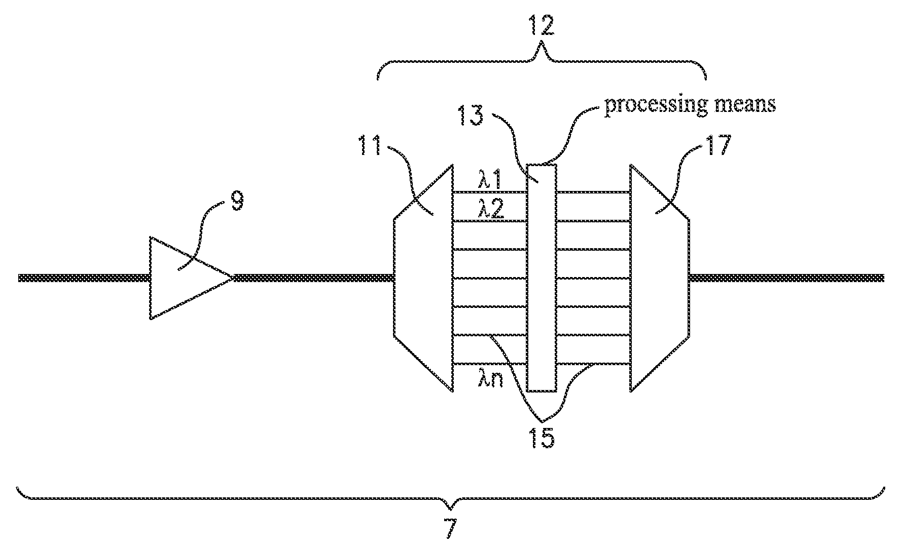
[0044]As used herein, the term “vulnerability characterizing parameter” of a connection refers to the lack of robustness of the connection with respect to degradation or impairments undergone by the signal along the connection. Different parameters may influence said vulnerability characterizing parameter such as[0045]the length of the connection,[0046]the modulation format along the connection,[0047]the bitrate of the connection,[0048]the format of the error correction code along the connection,[0049]the physical features of a link such as the type of optical fibers for example.

[0050]An idea of the embodiments of the present invention is to adjust individually the power levels of the different channels 15 of a link 7 in function of the features of the corresponding connections 1.

[0051]The adjustment is achieved by the determination, for each channel of the link, of a target power level corresponding to the power level producing the lowest signal degradation on the concerned channel...


PUM


Abstract

The present invention refers to a method for adjusting power levels of channels (15) in an optical link (7) of an optical network comprising at least one optical amplifier (9) wherein the power distribution among the channels (15) of the optical link (7) is achieved in function of:target power levels based on the features of corresponding connections and of link physical features,total available power in said at least one amplifier (9),features of control means allowing the power distribution,and wherein for a channel corresponding to a connection having a higher vulnerability characterizing parameter, the tolerated difference between an actual channel power level and the target power level is lower than for a channel corresponding to a connection having a lower vulnerability characterizing parameter.

Description

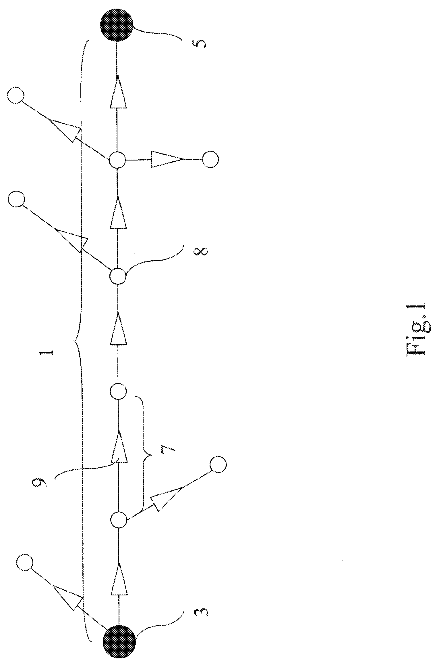
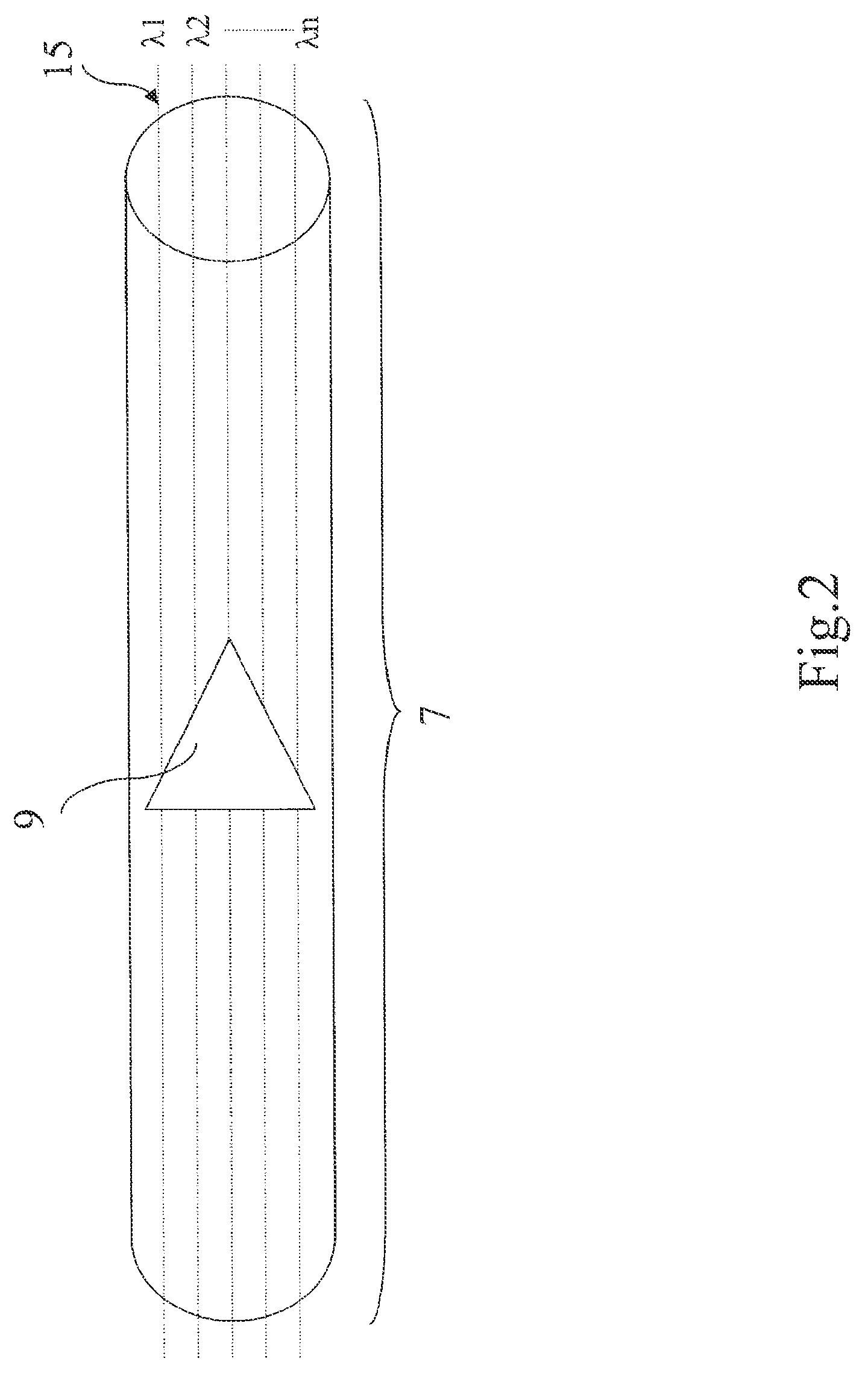
BACKGROUND OF THE INVENTION[0001]The present invention relates to the field of communication networks and in particular to optical communication networks.[0002]In such networks, signals are transmitted along a connection 1 on a given channel from an ingress node 3 to an egress node 5 through a plurality of links 7 and switching nodes 8, each link comprising at least one amplifier 9 as shown schematically in FIG. 1. Moreover, in a link, a plurality of channels 15 are transmitted and amplified together, each channel 15 corresponding to one wavelength as presented schematically in FIG. 2.[0003]The amplification power in the links has to be adjusted in order to optimize, for the connections involved in the link, the signal quality at destination. In the state of the art, equalization is achieved on the different channels such that all the channels of a link receive the same amount of power.[0004]Nevertheless, the known way to adjust power levels is not optimized.SUMMARY OF THE INVENTION...

Claims


Application Information

Patent Timeline
Patent Type & Authority Patents(United States)
IPC IPC(8): H04B10/293H04B10/27H04B10/296H04J14/02
CPCH04B10/2931H04B10/27H04B10/296H04J14/0221H04J14/02216
Inventor PELOSO, PIERREFABRE, ERICPECCI, PASCAL
Owner ALCATEL LUCENT SAS
Learn More