
Perfusion method and apparatus

a perfusion system and apparatus technology, applied in the field of perfusion methods and apparatuses, can solve the problems of lack of technical capability or work experience to cope, failure to maintain effective perfusion, insufficient or infrequent current teaching methods,

Active Publication Date: 2015-06-02
TERUMO CARDIOVASCULAR SYST CORP
View PDF23 Cites 11 Cited by
  • Summary
  • Abstract
  • Description
  • Claims
  • Application Information

AI Technical Summary

Benefits of technology

The present invention provides an apparatus for use with a perfusion system that includes a subject simulator for simulating the compliance and resistance of a subject's circulatory system. The apparatus includes a control system for manipulating the fluid properties of the perfusion system based on signals from sensors and a processing system for generating control signals. The apparatus can simulate a variety of health scenarios and can be used for training and testing purposes. The technical effects of the invention include improved control of fluid properties, better simulation of resistance and compliance, and more accurate simulation of blood loss and air entrainment.

Problems solved by technology

Management of cardiopulmonary bypass is therefore a complex time critical task and the risks of failing to maintain effective perfusion include patient injury or death.
An explanation for this lies in the potential for sudden major failures of the perfusion system demanding a prompt response from the perfusionist who due to lack of appropriate training may lack the technical capability or work experience to cope with unexpected medical emergency.
Both of these factors can be linked to the inadequate or infrequent current teaching methods.
Whilst a high degree of theoretical qualification is required, it is evident that very little actual practice of emergency responses is ever undertaken.
This is particularly a problem when faults occur such as obstructions occurring in the lines to the patient, power failures, equipment failure, or the like.
A further issue is that when new equipment is designed, there are only limited systems available to test the operation of the equipment before it must be used in a procedure to adequately assess its ability to provide adequate perfusion under all circumstances.
This in turn leads to a risk associated with the introduction of new equipment into perfusion procedures.

Method used


Image

  • Perfusion method and apparatus
  • Perfusion method and apparatus
  • Perfusion method and apparatus

Examples


Embodiment Construction

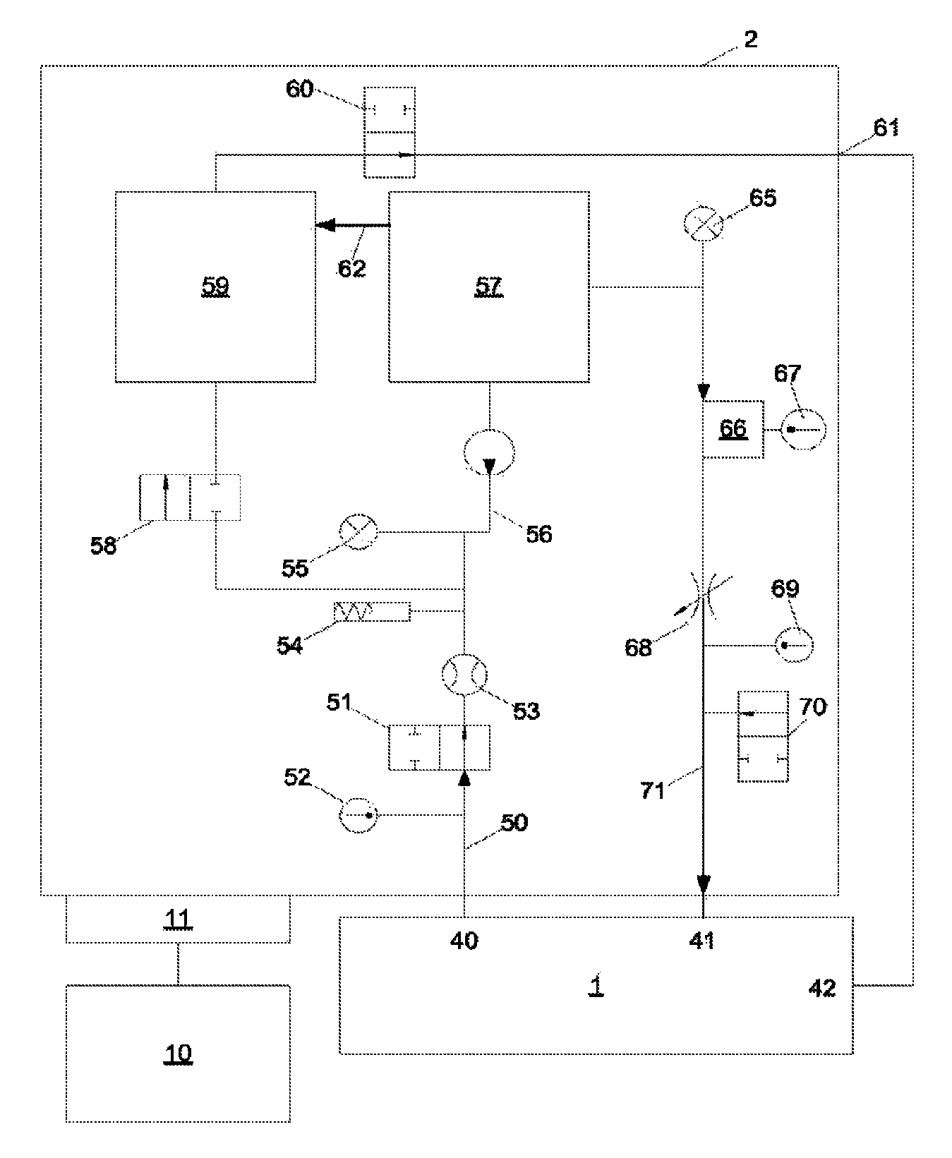
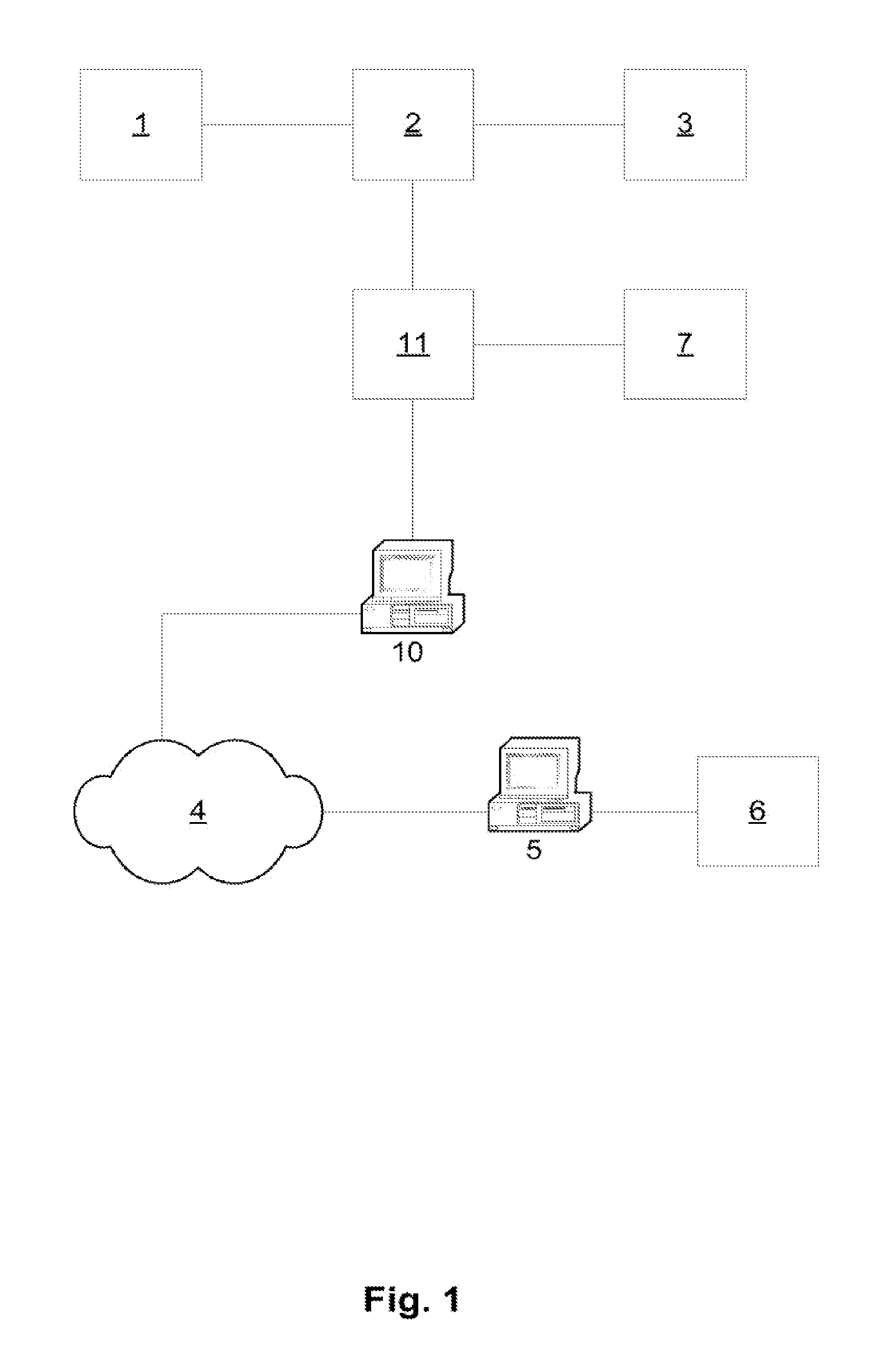
[0182]An example of apparatus for training a perfusion will now be described with reference to FIG. 1. In particular, as shown the apparatus includes an HLM 1 connected to a patient simulator 2, which is in turn connected to a patient monitor 3.

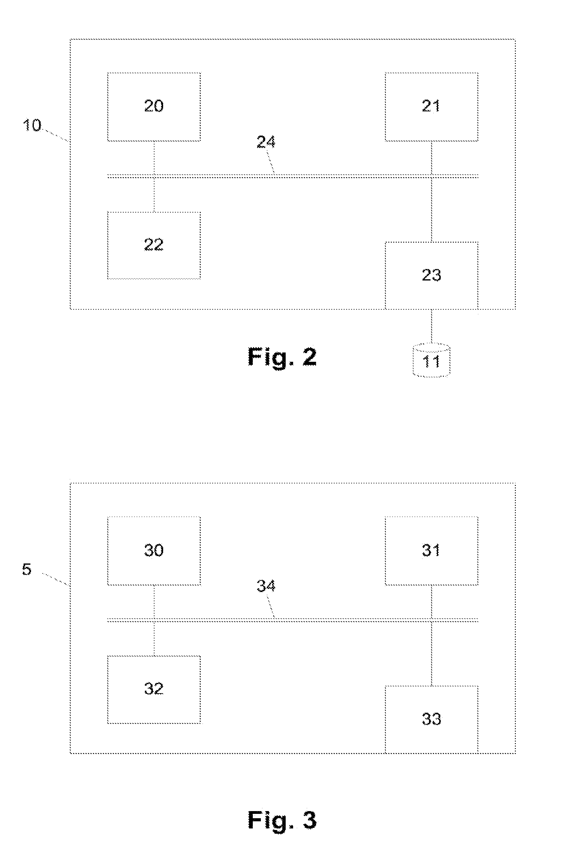
[0183]A processing system 10 is coupled to a controller 11, which is in turn coupled to the patient simulator 2 and ancillary equipment shown generally at 7.

[0184]An optional end station 5 and display 6 may be provided for use by a trainee, in which case the end station 5 is coupled to the processing system 10 via a suitable communications link 4, such as a communications network, wired or wireless connection, or the like.

[0185]In use, the patient simulator 2 operates to simulate the behaviour of a patient undergoing heart surgery to thereby allow the perfusionist to operate the HLM 1 in accordance with normal techniques which would be required during heart surgery procedures. The patient simulator 2 utilises a hydraulic system to represent b...


PUM


Abstract

Apparatus use with a perfusion system, the apparatus including a subject simulator for simulating subject. The subject simulator includes a circulatory system having an inlet line for receiving fluid from the perfusion system, an outlet line for transferring fluid to the perfusion system, at least on sensor for sensing at least one fluid property and at least one control device coupled to at least one of the inlet line and the outlet line. In use this, allows the control device to manipulate the at least on fluid property based at least partially on signals from the at least one sensor, to thereby simulate a least one of compliance and resistance of the simulated subject.

Description

BACKGROUND OF THE INVENTION[0001]The present invention relates to a method and apparatus for use with a perfusion system and in particular for training or assessing a perfusionist, testing perfusion equipment and demonstrating a perfusion process using a heart / lung machine.DESCRIPTION OF THE PRIOR ART[0002]The reference to any prior art in this specification is not, and should not be taken as, an acknowledgment or any form of suggestion that the prior art forms part of the common general knowledge.[0003]It is estimated that coronary heart disease will become the single biggest public health problem in the world by 2020. As a result of this the number of surgical procedures performed on the heart is increasing, and consequently there is a need for an increasing number of medical personnel trained in performing appropriate procedures.[0004]One particular process, known as cardiopulmonary bypass or perfusion is the process of replacing the actions of the heart and lungs with a mechanic...

Claims


Application Information

Patent Timeline
Patent Type & Authority Patents(United States)
IPC IPC(8): G09B23/28A61M5/32A61M5/44A61M5/46A61M5/48G09B23/30
CPCG09B23/285A61M5/44A61M5/486A61M5/445A61M5/484A61M5/48A61M5/321G09B23/28A61M5/46A61M5/488G09B23/30G09B23/303
Inventor PYBUS, ANDREWBEGG, JOHNMORRIS, RICHARDHERBERT, JAMES CRAIGILIC, VLADIMIRFULLER, STEPHEN RONALD
Owner TERUMO CARDIOVASCULAR SYST CORP
Learn More