Developments in or relating to a hand dryer

a technology of hand dryer and rib cage, which is applied in the field of hand dryers, can solve the problems of difficult accurate control of the width w of the slot c, and achieve the effects of reducing the number of stress risers in the rib cage, and reducing the risk of injury

Inactive Publication Date: 2015-06-16
DYSON TECH LTD
View PDF32 Cites 9 Cited by
  • Summary
  • Abstract
  • Description
  • Claims
  • Application Information

AI Technical Summary

Benefits of technology

[0007]The nozzle part does not require assembly—thus eliminating the adverse effects of tolerance stacking and making it easier to control the dimension of the outlet aperture.
[0008]This is particularly applicable to a hand dryer in which the outlet aperture is in the form of a narrow elongate slot—less than 1.5 mm in width (in particular less than 1 mm in width)—because work carried out in connection with this invention suggests that in these types of dryer, slot width is in fact a critical drying parameter: even very small variations in the slot width can have a significant effect on drying performance. Consequently, being able to eliminate the effects of tolerance stacking on the slot width in accordance with the invention makes it significantly easier to meet performance specification for these types of hand dryer.
[0009]Because the outlet aperture is post-machined, the method allows convenient moulding of the nozzle body—lending itself to economical use of injection-moulding, for example. This is particularly so in the case where the outlet aperture is a narrow elongate slot, which might require the use of relatively complicated moulding inserts to mould the slots.
[0012]By “plastic” is meant a thermosetting or thermoplastic polymer material. For example, the nozzle body may be moulded from Polycarbonate, or a blend of Polycarbonate and Acrylonitrile Butadiene Styrene, allowing convenient post-machining of the outlet aperture.
[0015]The bracing elements may be reinforcing ribs moulded on the inside of the part. These ribs effectively span the machined slot to brace the opposing walls of the slot. In this case, the post-machining step may be carried out using a radiused cutting tool which cuts part way into the reinforcing ribs. Cutting part way into the ribs helps prevent the ribs acting as dividing partitions in the slot whilst nevertheless retaining the bracing function of the ribs. Using a radiused cutting tool—such as a ball-nose or bull-nose cutter—has the advantage that it limits stress risers in the ribs. This is described in more detail below, with reference to some of the Figures.
[0016]The nozzle part may constitute, or form an integral part of, the external casing of the hand dryer. This provides for a simple construction in which the nozzle part is effectively integrated as part of the external casing of the hand dryer, making the dryer easier to clean and more hygienic.

Problems solved by technology

This lends itself to convenient injection-moulding of the two parts e, f but makes it difficult accurately to control the width W of the slot c due to tolerance stacking in the final assembly of the parts e, f.

Method used


Image

  • Developments in or relating to a hand dryer
  • Developments in or relating to a hand dryer
  • Developments in or relating to a hand dryer

Examples


Embodiment Construction

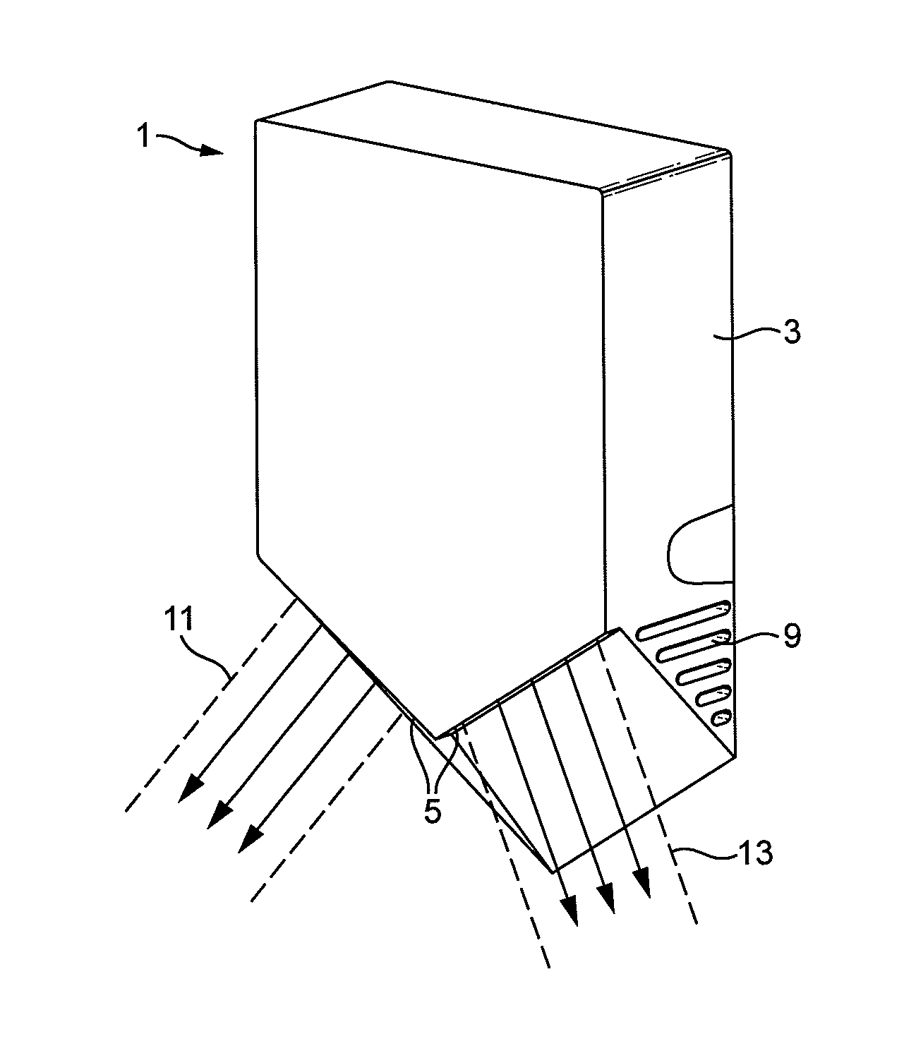
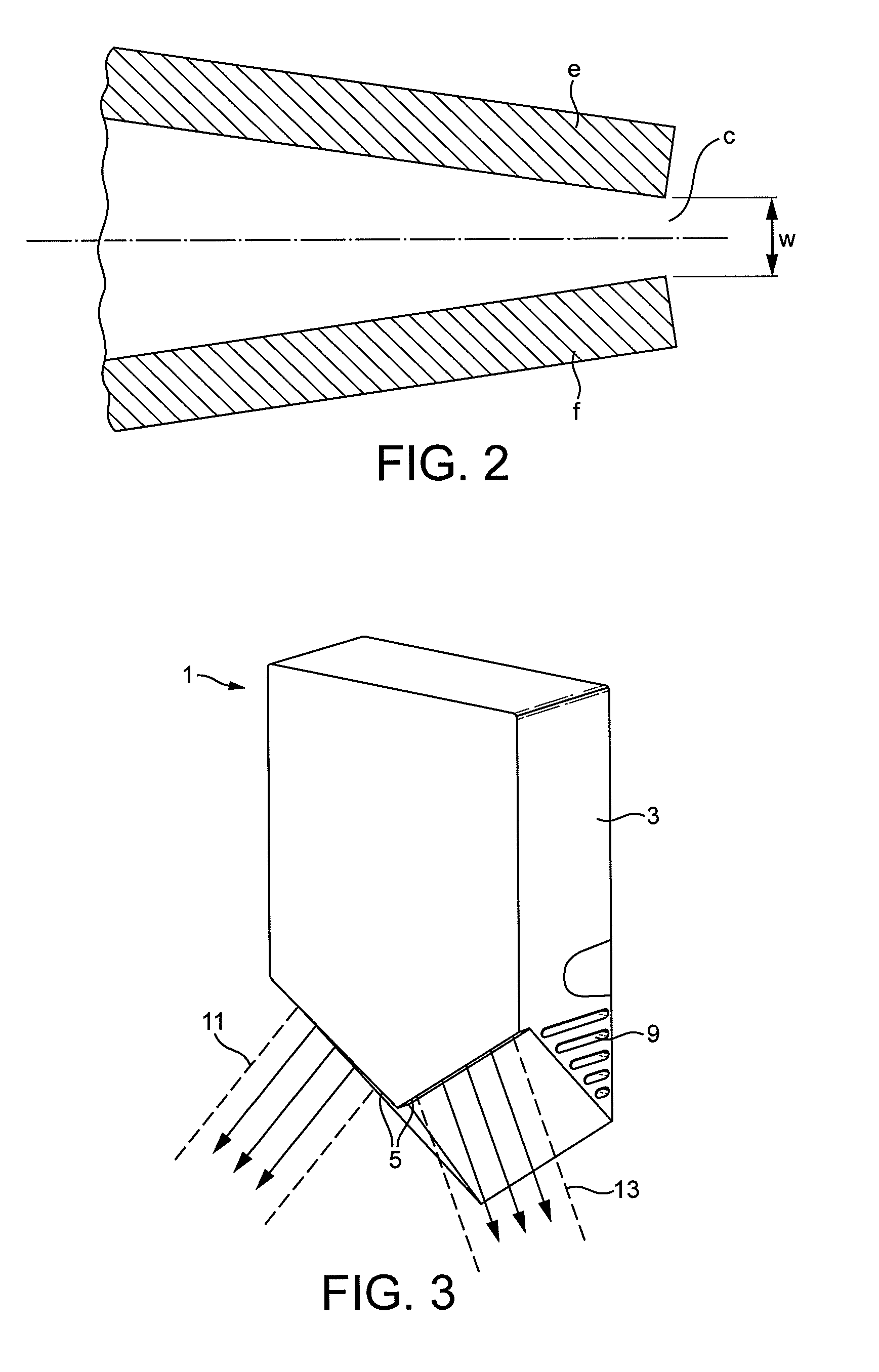
[0032]FIG. 3 shows a wall-mountable hand dryer 1 incorporating a nozzle part manufactured in accordance with the present invention. In this case, the nozzle part constitutes the main exterior casing 3 of the hand dryer, which incorporates a pair of outlet apertures in the form of narrow, elongate air slots 5—each approximately 0.8 mm in width. The air slots are not easily visible in FIG. 3, but one of the slots 5 is shown more clearly in FIG. 4, provided on an underside 7 of the dryer 1.

[0033]A motor-driven fan is provided inside the main casing 3, which draws air through intakes 9 on either side of the main casing 3 and forces the air at high speed (>100 m / s) out through the narrow elongate air slots 5.

[0034]Each of the elongate air slots 5 is sufficiently long to ensure that it spans the width of a typical user's hand when it is held—palm open—facing the slot 5. A length of between 120 mm and 160 mm is considered preferable for this. In use, the dryer 1 is mounted on a wall 17. Th...


PUM

PropertyMeasurementUnit
widthaaaaaaaaaa
lengthaaaaaaaaaa
widthaaaaaaaaaa

Abstract

A method of manufacturing a nozzle part for a hand dryer. The nozzle part has a nozzle body and an air outlet aperture in the nozzle body, and the method includes molding the nozzle body from plastic as a single part and then post-machining the air outlet aperture in the molded plastic nozzle body.

Description

REFERENCE TO RELATED APPLICATIONS[0001]This application claims the priority of United Kingdom Application No. 1118142.7, filed 20 Oct. 2011, the entire contents of which are incorporated herein by reference.FIELD OF THE INVENTION[0002]The present invention relates to the field of hand dryers.BACKGROUND OF THE INVENTION[0003]FIG. 1 shows a section through part of a conventional hand dryer, sold under the model name AB01 as part of the Dyson Airblade® range of hand dryers. This type of hand dryer is described in some detail in European Patent EP1909627. It works by forcing the drying air through two opposing, thin air slots—each less than 1 mm wide—to create opposing thin sheets of high velocity air, or “air-knives”, which act to strip water from the front and backs of a user's hands as they are ‘dipped’—palms flat—between the opposing air slots.[0004]The part a shown in FIG. 1 is one of the so-called air-knife assemblies on the hand dryer. There are two of these air-knife assemblies,...

Claims


Application Information

Patent Timeline
Patent Type & Authority Patents(United States)
IPC IPC(8): F26B21/00B29C45/00A47K10/48
CPCF26B21/004A47K10/48B29C45/0055B29C2793/009B29C2793/0009
Inventor DYSON, JAMESRYAN, LEIGH MICHAELCOX, ROBERT MICHAEL
Owner DYSON TECH LTD
Why Eureka
Try Eureka