
Tea cup and method of manufacturing a tea cup

a technology of tea cups and tea bags, applied in the field of tea cups, can solve the problems of difficult to get the right concentration of tea, difficult to clean tea bags and containers, and often not very tight containers containing tea materials, etc., and achieve the effects of reducing water movement efficiently, easy removal, and reducing water movemen

Inactive Publication Date: 2015-06-23
BOUGDANOS LAURA
View PDF16 Cites 2 Cited by
  • Summary
  • Abstract
  • Description
  • Claims
  • Application Information

AI Technical Summary

Benefits of technology

The invention is a tea cup with a detachable tea compartment that can be placed in different positions to make tea of sufficient strength. The shape of the cup and compartment allows for regulation of tea concentration and other functions like ceremonial and decoration. The tea cup provides a holistic experience with touch, visual impression, and odor, and allows for the enjoyment of tea for all senses. The tea cup is a modern answer to urban tea culture and provides a unique sensory experience.

Problems solved by technology

Problems with the existing solutions are the need for the hassling removal of the tea bag or the container from the tea before drinking, the unpractical filling and cleaning of the tea bags and containers and the difficulty of getting the right concentration of the tea.
In addition, the containers containing the tea material are often not very tight, whereby tea material runs to the tea water.

Method used


Image

  • Tea cup and method of manufacturing a tea cup
  • Tea cup and method of manufacturing a tea cup
  • Tea cup and method of manufacturing a tea cup

Examples


Embodiment Construction

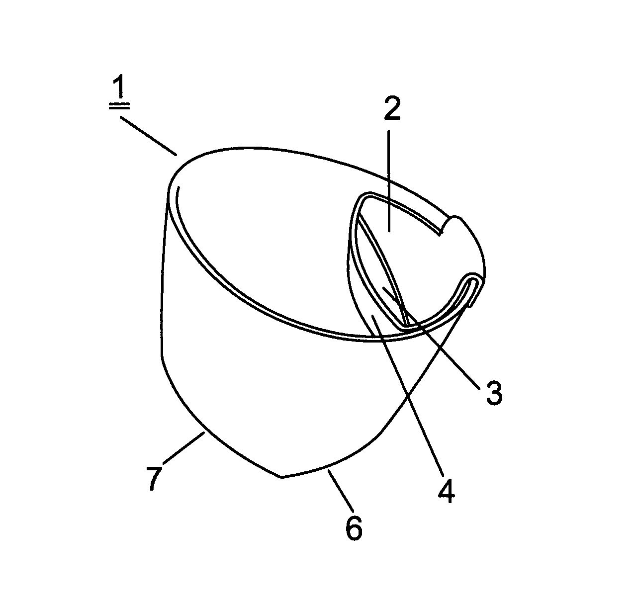
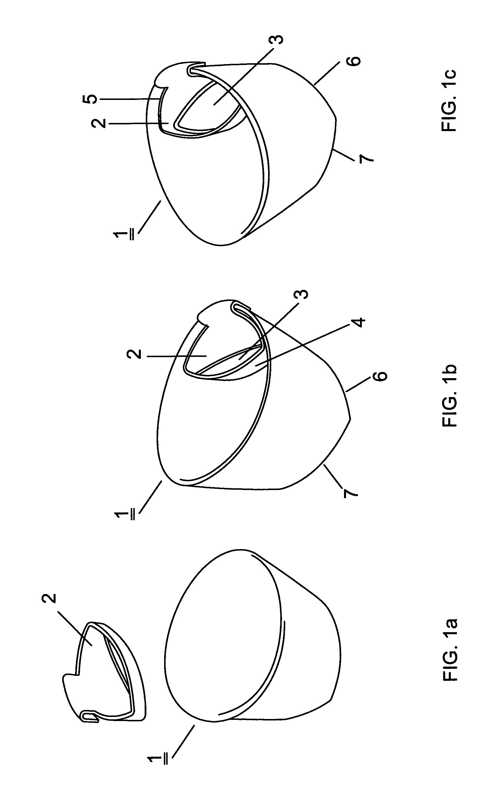
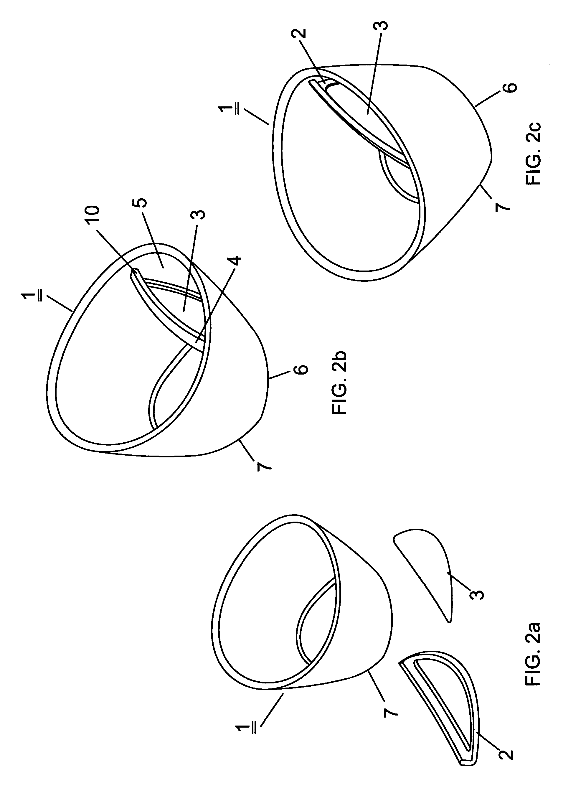
[0049]FIG. 1 shows an overall view of an embodiment of the tea cup of the invention seen from above. The tea cup 1 has a pocket part 2 with a sieve 3 for tea material. These two together 2, 3 form a tea compartment 4. The tea compartment 4 is attached to the inner wall 5 of the cup 1. The pocket part 2 can be attached to the inner wall 5 of the cup 1 even without the sieve 3, and the sieve 3 can be placed in the pocket afterwards. Part 2 is called pocket because, when attached to the inner wall 5 of the cup, it forms a pocket together with the inner wall 5. In this embodiment, the tea pocket 2 is detachably fastened to the inner wall of the tea cup 1. The two bottom sides on which the cup alternatively can lie on are indicated with reference numbers 6, 7. Preferably, there is a rim 10 at the edge of the tea compartment 4 to prevent tea leaves from falling while drinking tea if the tea compartment 4 is left in the cup 1 when drinking.

[0050]In FIG. 1a, the part forming the pocket 2 an...


PUM


Abstract

The tea cup (1) of the invention is used with a pocket (2) that includes a sieve (3) for tea material. The tea cup (1) has a functional shape achieved with two bottom sides (6,7) enabling the tea cup (1) to be placed in two different positions. The pocket (2) is designed so that it forms a tea compartment (4), which is attached to the inner wall (5) of the cup (1). The tea compartment (4) is integrally or detachably inserted in the tea compartment (4) at the upper part of the cup (1) on the same side as one of the bottom sides (6). This arrangement enables the tea compartment (4) to be on vertically different levels with respect to a water surface (or a tea surface) (11) in the cup (1) when the tea cup (1) is tilted in said different positions constituting a tea-making position and a drinking position in order to make tea of sufficient strength. The placement of the tea compartment (4) thus enables a functionality with respect to these positions. In the tea-making position, tea material inserted in the tea compartment (4) is in contact with the water in the cup (1), whereas in the drinking position, the tea material is intended to be above the water (or tea) surface (11). In the method of the invention for manufacturing the tea cup the tea cup part and the tea department part separately, whereafter a tea sieve is fastened to the tea compartment, and the tea compartment with the metal sieve is manufactured as a part that can be placed to the inner wall of the tea cup.

Description

CROSS-REFERENCE TO RELATED APPLICATIONS[0001]This application is an U.S. national phase application under 35 U.S.C. §371 based upon co-pending International Application No. PCT / FI2010 / 00066 filed on Oct. 29, 2010. Additionally, this U.S. national phase application claims the benefit of priority of co-pending International Application No. PCT / FI2010 / 00066 filed on Oct. 29, 2010 and Finland Application No. 20096124 filed on Oct. 29, 2009. The entire disclosures of the prior applications are incorporated herein by reference. The international application was published on May 5, 2011 under Publication No. WO 2011 / 051541A1.FIELD OF THE INVENTION[0002]The invention is concerned with a tea cup having a pocket with a sieve for tea material. The pocket is designed to form a tea compartment attached to the inner wall of the cup. The tea cup has a functional shape achieved with a V-like-shaped base, which enables the tea cup to be placed in two separate standing positions one for brewing and a...

Claims


Application Information

Patent Timeline
Patent Type & Authority Patents(United States)
IPC IPC(8): A47J31/00A47G19/22A47G19/16A47J31/06
CPCA47G19/22A47J31/0636A47G19/16A47G19/14
Inventor BOUGDANOS, LAURA
Owner BOUGDANOS LAURA
Learn More