Bone screw, method for manufacturing the bone screw, and tool for mounting and removing the bone screw

a manufacturing method and bone screw technology, applied in the field of bone screw manufacturing method, can solve the problems of uncompleted bone repositioning, joint dislocation for a second time or uncompleted bone repositioning, and inability to provide relative micro-motion and an external, etc., to achieve the effect of reducing the loosening probability of the bone screw, reducing the force received, and moderate elasticity

Active Publication Date: 2015-06-23
METAL INDS RES & DEV CENT
View PDF6 Cites 1 Cited by
  • Summary
  • Abstract
  • Description
  • Claims
  • Application Information

AI Technical Summary

Benefits of technology

[0010]The bone screw of the present invention has a fixing function in the case of a bone fracture or joint dislocation, and mainly has the following advantages. 1. The Young's modulus of the shaft portion is smaller than that of the front portion and that of the rear portion, thereby providing the bone screw with moderate elasticity. 2. After being fixed into two bones of the body, the bone screw can buffer and absorb the receiving force, thereby decreasing the force received by the bones when the front and rear portions are fixed therein, and further lowering the loosening probability of the bone screw. 3. The bone screw is integrally designed, so the wound after a surgery is small; and the bone screw respectively passes through and fixedly unites a first bone and a second bone, so as to reposition and fix the dislocated / fractured portion, thereby simplifying the surgical procedures and shortening the surgery duration.

Problems solved by technology

However, the shaft portion, the front portion, and the rear portion of the bone screw are integrally formed and manufactured with the same metal material, which fails to provide a relative micro-motion and an external buffer force between the two bones, and may further result in joint dislocation for a second time or uncompleted bone reposition when patients do exercise after the surgeries.
However, in the foregoing patent, as the front portion and the rear portion are merely connected by using surgical sutures, the surgery process is complicated, a large wound needs to be opened to perform an operation, and the fixation strength is undesirable.

Method used


Image

  • Bone screw, method for manufacturing the bone screw, and tool for mounting and removing the bone screw
  • Bone screw, method for manufacturing the bone screw, and tool for mounting and removing the bone screw
  • Bone screw, method for manufacturing the bone screw, and tool for mounting and removing the bone screw

Examples


Embodiment Construction

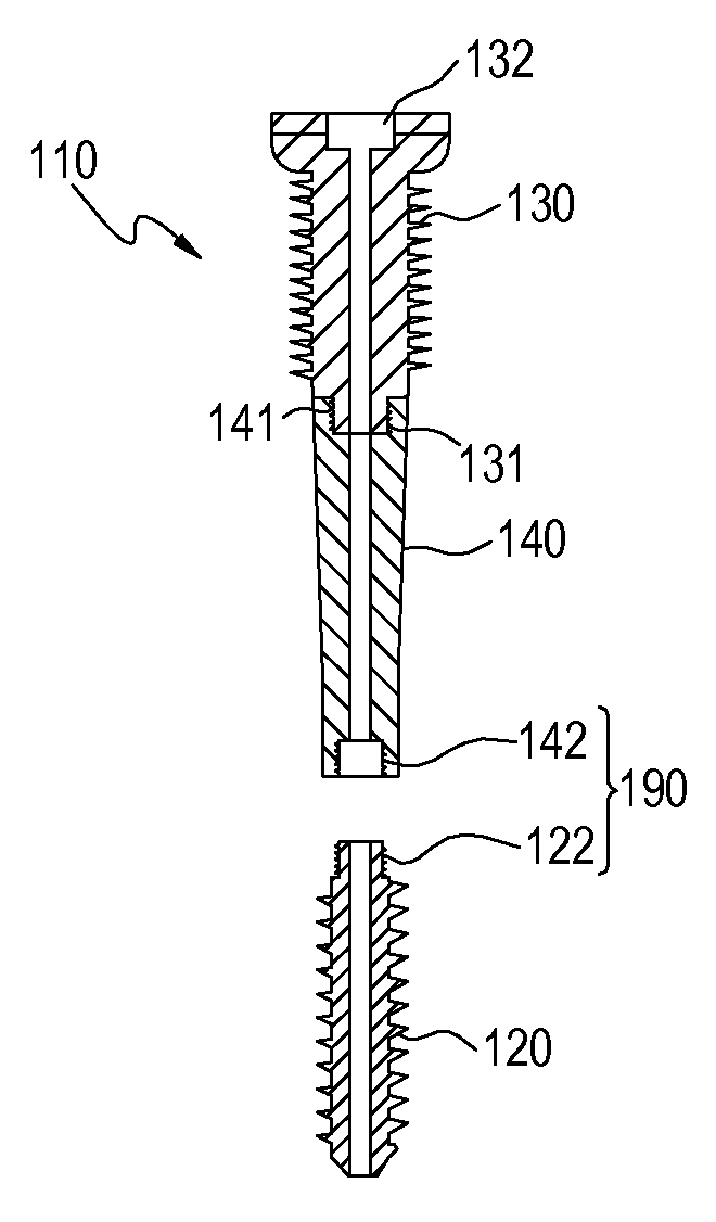
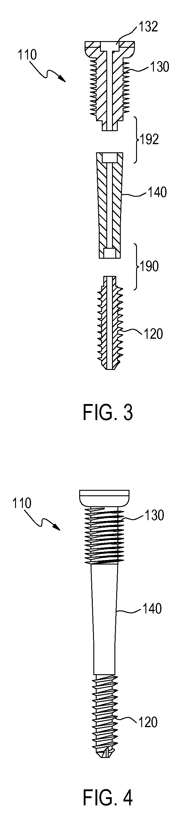
[0024]FIG. 3 and FIG. 4 show a method for manufacturing a bone screw according to a first embodiment of the present invention. Referring to FIG. 3, a front portion 120, a shaft portion 140, and a rear portion 130 are provided, wherein outer surfaces of the front portion 120 and the rear portion 130 are formed with threads. In this embodiment, preferably, the front portion 120, the shaft portion 140, and the rear portion 130 are all hollow inside and in communication with each other. The rear portion 130 includes a polygonal hole 132 located at a central line of the rear portion 130. The Young's Modulus of the shaft portion 140 is smaller than that of the front portion 120 and that of the rear portion 130. The front portion 120 and the rear portion 130 are fixedly joined to the shaft portion 140 through a joint structure 190 and a joint structure 192 respectively, so as to form an integral bone screw 110, as shown in FIG. 4. The joint structures 190 and 192 are used to respectively j...


PUM

PropertyMeasurementUnit
Young's Modulusaaaaaaaaaa
Young's modulusaaaaaaaaaa
population densityaaaaaaaaaa

Abstract

A bone screw includes a front portion, a rear portion, and a shaft portion. The shaft portion is fixedly joined to the front portion and the rear portion, so as to form an integral bone screw. The Young's modulus of the shaft portion is smaller than that of the front portion and that of the rear portion.

Description

CROSS-REFERENCE TO RELATED APPLICATION[0001]This application claims the benefit of Taiwan Patent Application No. 100141775, filed on Nov. 17, 2011, which is hereby incorporated by reference for all purposes as if fully set forth herein.BACKGROUND OF THE INVENTION[0002]1. Field of Invention[0003]The present invention relates to a method for manufacturing a bone screw, and a tool for mounting and removing the bone screw, and more particularly to a bone screw where the Young's modulus of a shaft portion is smaller than that of a front portion and that of a rear portion.[0004]2. Related Art[0005]The work and life style in most areas of Asia is characterized in high population density, a great many motor vehicles, intensive labor forces, and gradually aging population. In recent years, the Asian economic environment and conditions are improved. In addition, the Asian body type is different from that of the westerners, and the causes of bone trauma in Asia are different from those in Euro...

Claims


Application Information

Patent Timeline
Patent Type & Authority Patents(United States)
IPC IPC(8): A61B17/86A61B17/88
CPCA61B17/8685A61B17/866A61B17/8875Y10T29/49826A61B17/864
Inventor CHIEN, CHI-SHENGYU, TSUNG-CHIHYU, CHUNG-HSINGKUO, SHIEN-NAN
Owner METAL INDS RES & DEV CENT
Why Eureka
Try Eureka