Boiling water reactor core shroud head bolt retainer tool

a technology for water reactors and retainers, which is applied in the direction of manufacturing tools, greenhouse gas reduction, nuclear elements, etc., can solve the problem that the retainer may not return to the locked position

Inactive Publication Date: 2015-06-23
AREVA INC
View PDF15 Cites 2 Cited by
  • Summary
  • Abstract
  • Description
  • Claims
  • Application Information

AI Technical Summary

Problems solved by technology

Due to many years of service, and with the accumulation of grit and grime, the retainers may not return to the locked position with just spring pressure.

Method used


Image

  • Boiling water reactor core shroud head bolt retainer tool
  • Boiling water reactor core shroud head bolt retainer tool
  • Boiling water reactor core shroud head bolt retainer tool

Examples


Embodiment Construction

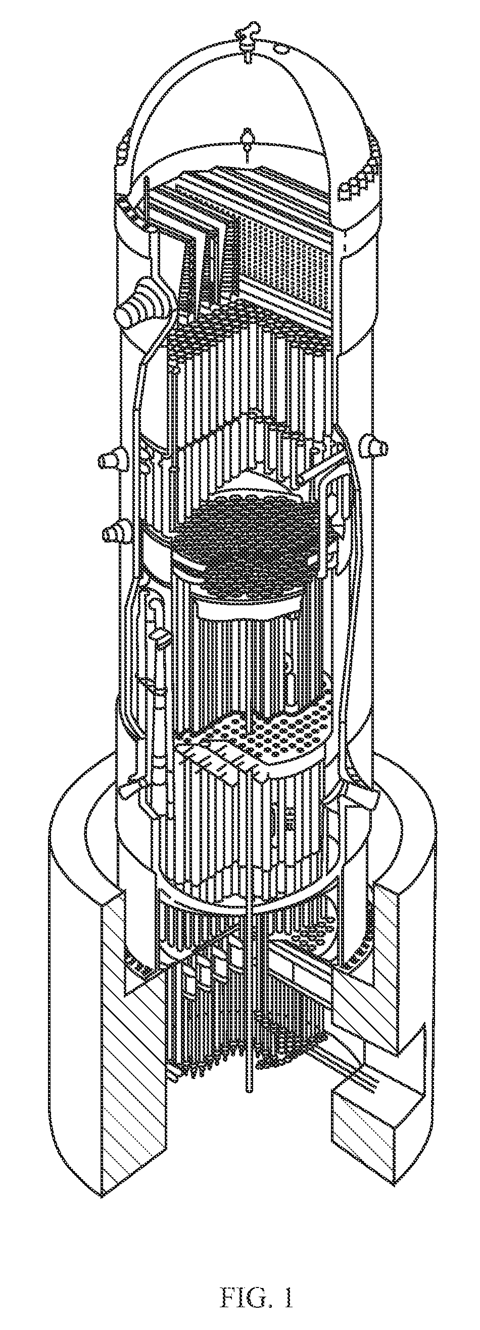
[0013]In a typical commercial boiling-water reactor, such as illustrated in FIG. 1, the core inside the reactor vessel creates heat, a steam-water mixture is produced when water (reactor coolant) moves upward through the core, absorbing heat. The steam-water mixture leaves the top of the core and passes through moisture separation equipment where water droplets are removed before the steam is allowed to enter the steam line. The steam line directs the steam to the main turbine, causing it to turn the turbine generator, which produces electricity. The unused steam is exhausted into the condenser where it is condensed into water. The resulting water is pumped back to the reactor vessel.

[0014]The reactor core contains fuel assemblies that are cooled by water circulated therethrough. A majority of coolant flows down through an annul us created between the reactor vessel wall and the core shroud 1, while a portion of the coolant is directed through jet pumps located within the annulus th...


PUM

PropertyMeasurementUnit
diameteraaaaaaaaaa
lengthaaaaaaaaaa
repositioning forceaaaaaaaaaa

Abstract

The inventive tool is designed to ensure proper plant operation position of the core shroud head bolt assemblies of a boiling water nuclear reactor. The tool exerts an upward pulling force on stuck retainers to return them to the locking position around the nut. The tool includes a frame, an engagement member, and a collar. The engagement member is lowered toward and end of the bolt until it comes into contact therewith. Further movement of the engagement member causes the frame and collar to move upward, lifting the retainer and extending the spring.

Description

CROSS-REFERENCE TO RELATED APPLICATIONS[0001]This patent application claims the benefit of U.S. Provisional Patent Application No. 61 / 522,511 filed on Aug. 11, 2011, which is incorporated herein by reference in its entirety.BACKGROUND OF THE INVENTION[0002]1. Field of the Invention[0003]The present invention relates to a boiling water reactor core shroud head bolt removal tool, and, more particularly, the present invention relates to a tool for ensuring safe removal and installation of core shroud head bolts to the proper position.[0004]2. Description of the Related Art[0005]Core shrouds are components of boiling water nuclear reactors; they are cylindrical structures that surround the core to provide a barrier to separate the downward coolant flow through the annulus from the upward flow through the core. The core shrouds also structurally support and align the fuel assemblies, steam separator assemblies, and control rod guide tubes. A head sits atop the shroud and creates an upper...

Claims


Application Information

Patent Timeline
Patent Type & Authority Patents(United States)
IPC IPC(8): B23P19/00B23P19/04B25B27/14B25B29/02B25B27/02G21C19/20
CPCB25B27/023G21C19/20Y10T29/531Y10T29/49826G21C19/207Y02E30/30B23P19/048
Inventor COCKE, JASON B.
Owner AREVA INC
Why Eureka
Try Eureka