Coilable shade

a shade and coiling technology, applied in the field of coiling shade, can solve the problems of increasing costs, failure to provide reliable coiling or uncoiling, etc., and achieve the effects of reducing costs, reducing costs, and reducing costs

Active Publication Date: 2015-06-23
KO HOU SHENG
View PDF9 Cites 17 Cited by
  • Summary
  • Abstract
  • Description
  • Claims
  • Application Information

AI Technical Summary

Benefits of technology

[0007]An objective of the present invention is to provide a coilable shade to mitigate and / or obviate the above disadvantages including rapid coiling of the shade, large volume, and high costs resulting from insufficient frictional force of frictional pads that fails to position the shade in a desired location and resulting from the hydraulic buffering device required for buffering the shade.
[0010]The at least one soft ring buffer of the control device according to the present invention can drive the rotating member to change the position of the track for unfolding, coiling, and positioning of the shade. Furthermore, the rotational friction force of the rotating member and the buffering effect during coiling of the shade can be increased, allowing easy operation and easy adjustment.
[0011]The overall outer diameter of the control device according to the present invention is as small as 1.5 cm after assembly, which is not only suitable for coilable shades on doors and windows but also suitable for small shades used on doors of automobiles, providing a wider application.

Problems solved by technology

If the frictional force of the friction pads 135 is insufficient, the shade 17 coils rapidly and causes noise.
(1) The friction pads 135 of the pull / coil device 13 provide insufficient friction such that the friction pads 135 can not easily drive the rotating member 133 to change the position of a track 136 on the rotating member 133, failing to provide reliable coiling or uncoiling of the shade 17.
(2) The friction pads 135 are received in recesses 1331 in an inner periphery of the rotating member 133, and the sleeve 134 is then inserted into the rotating member 133 so that the outer periphery of the sleeve 134 contacts with the friction pads 135. The overall diameter of the pull / coil device 13 is 3 cm, which is too large to be used in a small shade mounted to a door of an automobile, providing limited application.
(3) The hydraulic buffering device 14 is a necessity to the coilable shade I for buffering the shade 17, increasing the costs.

Method used


Image

  • Coilable shade
  • Coilable shade
  • Coilable shade

Examples


Embodiment Construction

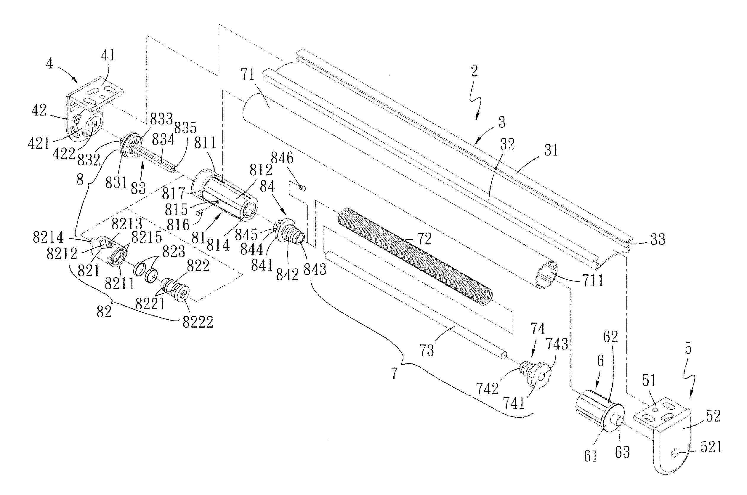
[0020]With reference to FIGS. 4-7, a coilable shade 2 according to the present invention includes a main frame 3 having two upwardly extending abutment sides 31 and 32, with the abutment sides 31 and 32 opposite to each other. A channel 33 is defined between two inner faces of the abutment sides 31 and 32.

[0021]The coilable shade 2 further includes left and right fixed seats 4 and 5 opposite to each other and respectively mounted to left and right sides of the main frame 3. The left fixed seat 4 includes a left fixed board 41 and a left positioning board 42 extending downward from an outer end of the left fixed board 41. The right fixed seat 5 includes a right fixed board 51 and a right positioning board 52 extending downward from an outer end of the right fixed board 51. The left and right fixed boards 41 and 51 are inserted into the channel 33 defined between the abutment sides 31 and 32 of the main frame 3. Each of the left and right fixed boards 41 and 51 has a plurality of fixi...


PUM


Abstract

A coilable shade includes a main frame to which left and right fixed seats are mounted. A drum is rotatably coupled to the right fixed seat and receives a spring receiving a shaft extending through a positioning seat. An end of the coiling spring is fixed to the positioning seat. The other end of the coiling spring is fixed to a connection seat mounted to the left fixed seat. A rotating unit is mounted in a jacket and rotatably coupled to a positioning rod fixed to the left fixed seat. A fastener is slideable along a track in a rotating member of the rotating unit to control unfolding, coiling, and positioning of a shade. The rotating unit further includes a sleeve received in the rotating member. A soft ring buffer is received in an annular groove of the sleeve and contacts an inner periphery of the rotating member.

Description

BACKGROUND OF THE INVENTION[0001]The present invention relates to a coilable shade and, more particularly, to a coilable shade including a soft ring rubber to drive a rotating member to change a position of a track in the rotating member for controlling unfolding, coiling, and positioning of a shade as well as increasing the rotational frictional force of the rotating member and providing the buffering effect while coiling the shade.[0002]A plurality of types of coilable shades available in the market is generally used on doors and windows in houses and offices to shield the sun as well as providing a decoration effect. FIGS. 1-3 show a conventional coilable shade 1 including a main frame 11, a coiling device 12, a pull / coil device 13 mounted to a left side of the main frame 11, a hydraulic buffering device 14 mounted to a right side of the main frame 11, and left and right fixed seats 15 and 16. In a case that the shade 17 is moved downward to a position, a coiling spring 131 at a ...

Claims


Application Information

Patent Timeline
Patent Type & Authority Patents(United States)
IPC IPC(8): E06B9/56E06B9/60E06B9/90B60J1/20E06B9/42E06B9/80
CPCE06B9/60E06B9/42B60J1/2033B60J1/205E06B9/90E06B2009/807E06B9/50
Inventor CHEN, SHIH-YUAN
Owner KO HOU SHENG
Why Eureka
Try Eureka