Methods and apparatus for mitigating interference between co-located collaborating radios

a technology of co-location and radio, applied in the field of wireless communication base stations and mobile devices, can solve the problems of undesirable radio interference between communications, inability to eliminate oobe completely, and energy from the lte network to leak into the lmr network

Active Publication Date: 2015-06-23
MOTOROLA SOLUTIONS INC
View PDF22 Cites 10 Cited by
  • Summary
  • Abstract
  • Description
  • Claims
  • Application Information

AI Technical Summary

Problems solved by technology

Because the foregoing commercial operator spectrum allocations are spectrally near the legacy narrow band voice band, some of the energy from the LTE network may “leak” into the LMR network.
Under certain conditions, this leakage, known as out of band emissions (OOBE), may cause undesirable radio interference to communications between an LMR base station and one or more of its mobile devices, particularly when the LMR mobile device is geographically co-located (e.g., in the same police car or fire truck) with the interfering LTE mobile device (mobile station).
Those skilled in the art will appreciate that radio frequency tuning equipment, such as band pass filters, can selectively determine a desired frequency range to be transmitted; however, they are expensive and typically cannot eliminate OOBE entirely.
Transmissions between an LTE VSM and its LTE eNB may result in undesirable OOBE at a co-located LMR mobile device.
More particularly, when an LMR mobile device is advised by its LMR base station that a call is being initiated, the LMR radio sends an alert signal to its co-located LTE radio, including an indication of the maximum amount of interference the LMR radio can accept from the LTE radio without the OOBE from the LTE UE resulting in interference to the narrow band call at the co-located LMR mobile device.
Blocking is different from OOBE in that OOBE relates to power from a transmitter that is actually outside of the transmitter's channel, and increases the noise level on nearby frequencies.

Method used


Image

  • Methods and apparatus for mitigating interference between co-located collaborating radios
  • Methods and apparatus for mitigating interference between co-located collaborating radios
  • Methods and apparatus for mitigating interference between co-located collaborating radios

Examples


Embodiment Construction

[0013]The Federal Communications Commission (FCC) is responsible for allocating the finite radio frequency spectrum among various government entities, cellular telephone and data carriers, and a host of competing corporate and individual interests. In that capacity, the FCC has allocated certain frequency bands for use by and for the benefit of local, state, and national public safety organizations and applications.

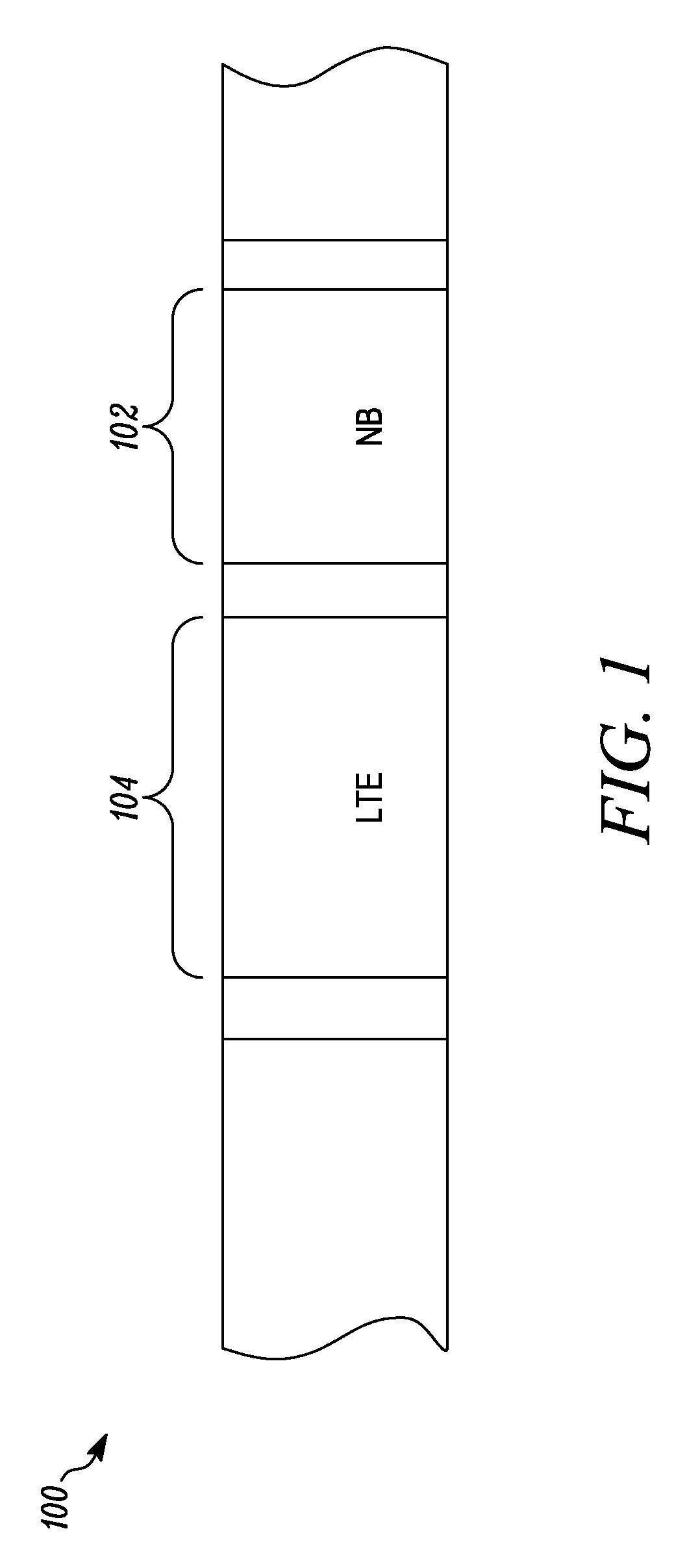
[0014]In particular, the frequency band including 799 to 805 megahertz (MHz) and paired with 769 to 775 MHz has been allocated for public safety (PS) narrowband (NB) voice communications by police, fire, and other emergency response teams. These frequencies support “push-to-talk” land mobile radio (LMR) two-way radio devices used by law enforcement agencies across the country.

[0015]The FCC has also designated the frequency band from 793 to 798 MHz and paired with 763 to 768 MHz for broadband public safety transmissions. The FCC has mandated the use of 3GPP Long Term Evolu...


PUM


Abstract

Methods and apparatus are provided for mitigating interference between spectrally distinct wireless communication networks employing co-located, collaborating radios. A first base station is in a first network and communicates with a first radio within a first frequency range, and a second base station is in a second network and communicates with a second radio in a second frequency range. The first and second radios are geographically co-located, for example, within a public safety vehicle. The first radio determines a maximum level of interference it will accept based on current operational parameters, and communicates a corresponding threshold value to the second radio through a data link. The second radio sends a request to its base station to employ interim scheduling constraints governing uplink transmissions from the second radio, to thereby limit out of band emissions received by the first radio to a range that is less than the threshold interference level.

Description

FIELD OF THE DISCLOSURE[0001]The present disclosure relates generally to wireless communication base stations and mobile devices, and more particularly to methods and apparatus for mitigating out of band emissions among user equipment and base stations operating at geographically co-located and spectrally distinct wireless communication systems.BACKGROUND[0002]Hurricanes, tornadoes, floods, and other natural disasters, as well as other life-threatening emergencies, underscore the need for a robust communications infrastructure for use by local, state, and federal emergency response teams. Police departments, fire departments, “911” call centers and other law enforcement personnel increasingly rely upon mobile wireless communication devices (also referred to herein as “user equipment” or “UE”), typically dash-mounted or hand-held radios, to coordinate first response and “on scene” rescue efforts with citizens, dispatchers, and fellow public safety organizations.[0003]The proliferatio...

Claims


Application Information

Patent Timeline
Patent Type & Authority Patents(United States)
IPC IPC(8): H04W4/00H04W72/12H04W4/90
CPCH04W72/1215H04W72/1284H04W72/21
Inventor ANDERSON, JEFF S.ANDERSON, HENRY W.HIBEN, BRADLEY M.
Owner MOTOROLA SOLUTIONS INC
Why Eureka
Try Eureka