Wireless power transmission device

a power transmission device and wireless technology, applied in the direction of transformer/inductance circuit, circuit arrangement, inductance, etc., can solve the problems of control errors and instability of wireless charging modules, the inability to apply higher power transfer, and the interference becomes more sever

Active Publication Date: 2015-06-30
AU OPTRONICS CORP
View PDF19 Cites 1 Cited by
  • Summary
  • Abstract
  • Description
  • Claims
  • Application Information

AI Technical Summary

Benefits of technology

[0007]Due to the fact that the RFID feedback signal's operating frequency is about several megahertz (MHz) and the RFID feedback signal is transmitted via the same inductive coils used to transmit power, the same inductive coils are required to transfer power and the RFID feedback signal. Thus the RFID feedback signal waveforms may be distorted by voltages induced by the power transmission on the inductive coils, thereby interfering the RFID feedback signal and causing control errors and instability of the wireless charging module 100. The higher the power transmission is, the more severe the interference becomes. As a result, applications of wireless charging technology are limited and cannot be applied to higher power transfer.

Problems solved by technology

Thus the RFID feedback signal waveforms may be distorted by voltages induced by the power transmission on the inductive coils, thereby interfering the RFID feedback signal and causing control errors and instability of the wireless charging module 100.
The higher the power transmission is, the more severe the interference becomes.
As a result, applications of wireless charging technology are limited and cannot be applied to higher power transfer.

Method used


Image

  • Wireless power transmission device
  • Wireless power transmission device
  • Wireless power transmission device

Examples


Embodiment Construction

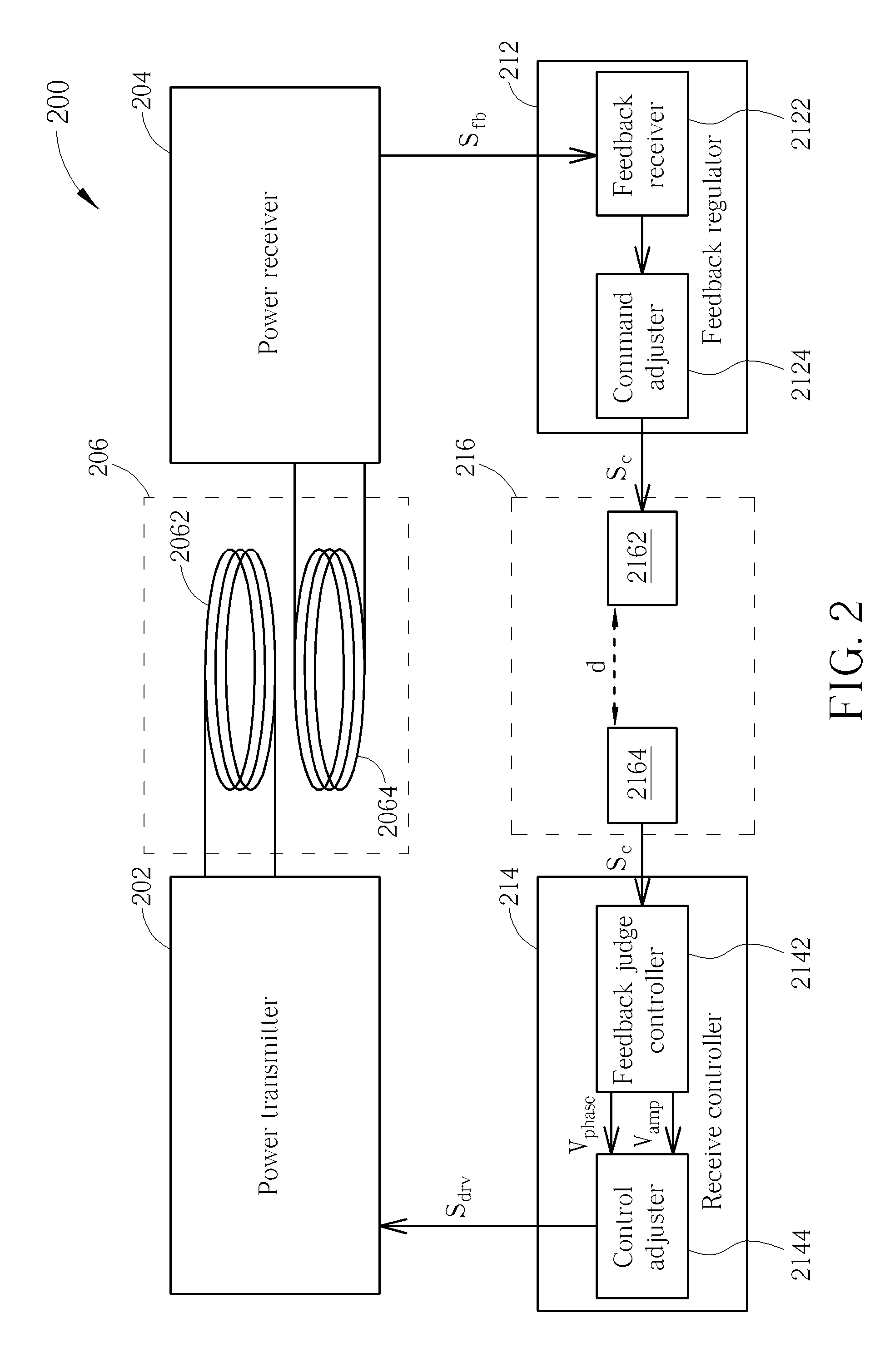
[0035]Please refer to FIG. 2, which is a diagram illustrating a wireless power transmission device 200 according to an embodiment of the present invention. The wireless power transmission device 200 may include a power transmitter 202, a first transmission unit 206, a power receiver 204, a feedback regulator 212, a receive controller 214, and a second transmission unit 216. The first transmission unit 206 may include a first inductive element 2062 and a second inductive element 2064. The feedback regulator 212 may include a feedback receiver 2122 and a command adjuster 2124. The receive controller 214 may include a feedback judge controller 2142 and a control adjuster 2144. The second transmission unit may include a first conductive element 2162 and a second conductive element 2164.

[0036]The power transmitter 202 is used to convert DC voltage to AC voltage having a predetermined frequency and amplitude. FIG. 3A is a diagram illustrating the power transmitter 202 according to an embo...


PUM

PropertyMeasurementUnit
poweraaaaaaaaaa
rectified output voltageaaaaaaaaaa
phaseaaaaaaaaaa

Abstract

A wireless power transmission device includes a power transmitter, a first transmission unit, a power receiver, a feedback regulator, a receive controller, and a second transmission unit. The power transmitter is for generating power, and the first transmission unit is for wirelessly transmitting power generated by the power transmitter. The power receiver is for receiving and rectifying the power from the first transmission unit. The feedback regulator is for receiving a feedback signal from the power receiver to generate an AC control signal. The receive controller is for receiving the control signal to generate a driving signal. The second transmission unit is for wirelessly transmitting the control signal to the receive controller.

Description

CROSS-REFERENCE TO RELATED APPLICATIONS[0001]This application claims the benefit of priority to Taiwan Patent Application No. 101135998, filed Sep. 28, 2012 and now Taiwan Patent No. 1473382, both included herein by reference in their entireties.BACKGROUND OF THE INVENTION[0002]1. Field of the Invention[0003]The present invention is related to a wireless power transmission device, and more particularly, to a wireless power transmission device having feedback control.[0004]2. Related Art[0005]Wireless charging technology which utilizes non-contact wireless power transmission has been widely applied to mobile devices such as consumer electronics, smart phones, and tablet computers.[0006]Please refer to FIG. 1. FIG. 1 is a diagram illustrating a prior art wireless charging module 100. The wireless charging module 100 includes a power transmitter 102, a power receiver 104, and a transmission unit 106. The transmission unit 106 utilizes inductive coils 108 and 110 as an antenna for trans...

Claims


Application Information

Patent Timeline
Patent Type & Authority Patents(United States)
IPC IPC(8): H02M7/06H01F27/42H01F37/00H01F38/00H02J5/00
CPCH02M7/06H02J5/005H02J50/10
Inventor LIN, HUANG-TILI, YUEH-HANLEE, TSUNG-SHIUNLIU, JIA-WEI
Owner AU OPTRONICS CORP
Why Eureka
Try Eureka