Distribution chute for a charging device

a charging device and discharging chute technology, which is applied in the direction of charging devices, charge manipulation, lighting and heating apparatus, etc., can solve the problems of affecting the operation of the charging device, and requiring a rather complex mounting and dismounting procedure, so as to avoid significant torque reversal and facilitate the mounting and dismounting of the chute

Active Publication Date: 2015-07-07
PAUL WURTH SA
View PDF20 Cites 4 Cited by
  • Summary
  • Abstract
  • Description
  • Claims
  • Application Information

AI Technical Summary

Benefits of technology

[0008]The invention provides a chute configuration that further facilitates mounting and dismounting of the chute to a charging device and avoids significant torque reversal onto the support structure of the chute during operation.
[0018]In a robust design, the mounting head is of annular circumferentially closed configuration and the suspensions are integrally formed with the mounting head so as to protrude laterally and oppositely away from the central chute axis at the height of the suspensions. In a preferred embodiment, the suspensions may be integrally cast together with a mounting head made of cast metal, e.g. cast iron or cast steel.
[0019]For increased safety, the suspensions and support flanges may comprise at least one safety pin and a cooperating pin hole. In normal operation of the charging device, torque exerted by gravity about the tilt axis (i.e. the line passing through the tilt points) secures the chute to the support flanges and thus prevent the chute from dropping into the metallurgical reactor. Accordingly, the safety pin is not necessary under normal circumstances. However, the safety pin may be useful for preventing an accidental movement of the chute, e.g. in case of an explosion in the metallurgical reactor, which could cause the chute suspensions to disengage from the support flanges. The safety pin preferably has an axis coinciding with the tilt axis to avoid torque exerted thereon.
[0021]In a chute design that is particularly suitable for a replacement along the vertical without reduction of charging radius, the upstream mounting head is bent so that it has a central axis at a bend angle with respect to the longitudinal axis, the bend angle measuring from 15° to 45°, preferably from 20° to 40°. With this kind of design, in chute replacement position, the downstream longitudinal axis is preferably at an angle to the vertical, that ranges from 0° to +5° when measured in the raising sense. Preferably, the elongated downstream chute portion is of conical or cylindrically tubular and circumferentially closed configuration and fixed to the mounting head. In order to permit pivoting the chute to a radially further outward charging position in the raising sense, the mounting head preferably comprises a recess that avoids impact on the charging device in the radially outermost chute position.
[0023]Thanks to of the new chute configuration, the tilt axis about which the weight of the chute exerts torque onto the support flanges may be offset from the pivoting axis, so as to avoid modification in the pivoting mechanism. When seen in a horizontal plane, with a chute as set out above, the tilt axis may thus be offset from the pivoting axis, namely toward the main sliding surface of the chute body.

Problems solved by technology

However, they require a rather complex mounting and dismounting procedure.
Accordingly, considerable chute weight plus that of sliding charge material exerts considerable torque onto the support flanges of the charging device.
This torque would naturally tend to jam the chute with respect to the support flanges.
As will be understood from the foregoing however, commonly used chute suspension designs, e.g. of “duckbill-shaped” or hook-shaped configuration, are usually of complex shape, which in turn renders intricate or complex the movement or relative motion needed for mounting and dismounting.
In addition to complex geometries of the suspension and of the support flange, the tilting torque that the chute weight exerts onto the support flanges impedes mounting and dismounting.
Even with a simplified suspension design according to U.S. Pat. No. 5,022,806 however, the tilting torque of the chute onto the support flanges still hampers mounting and dismounting.

Method used


Image

  • Distribution chute for a charging device
  • Distribution chute for a charging device
  • Distribution chute for a charging device

Examples


first embodiment

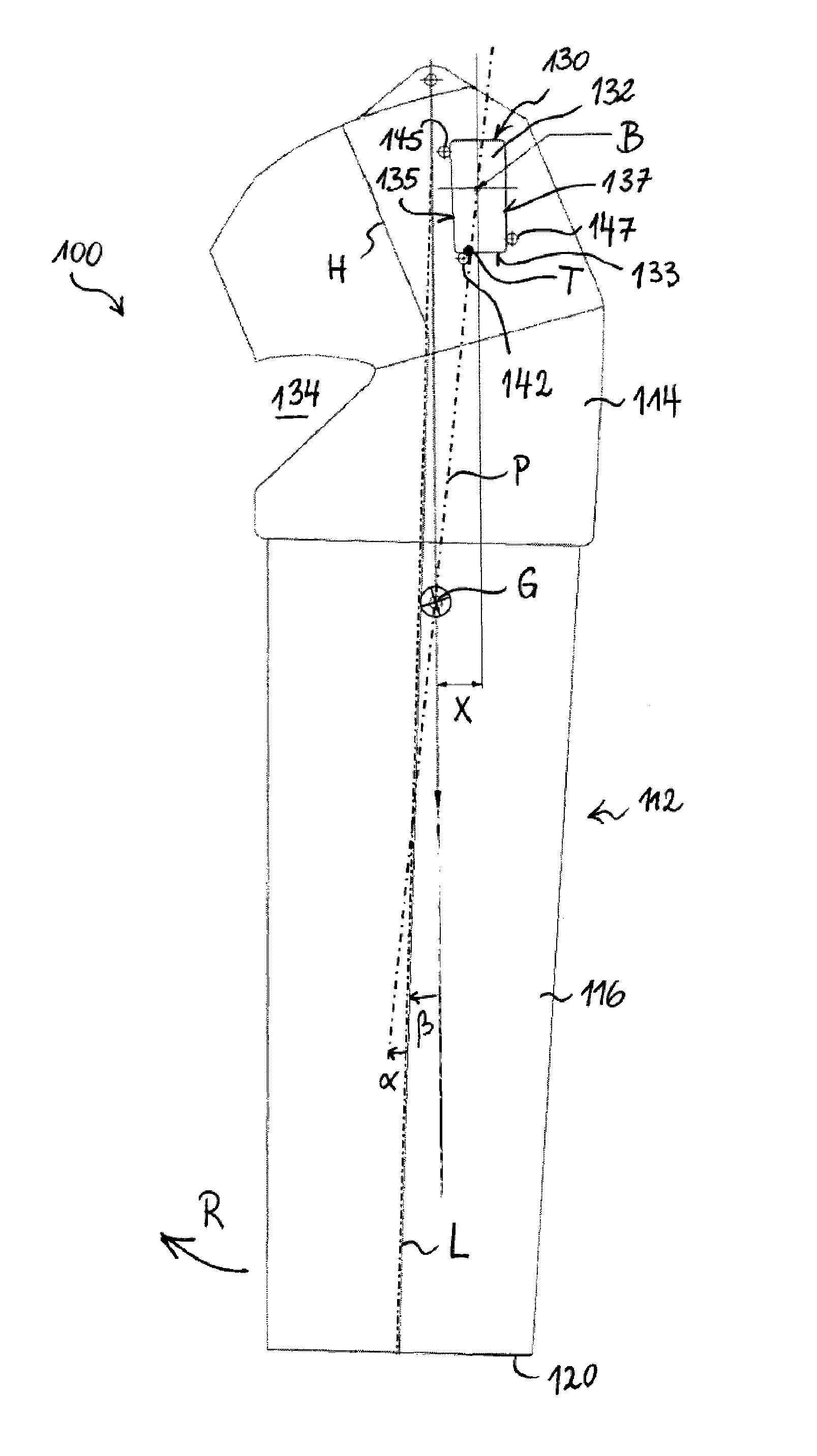
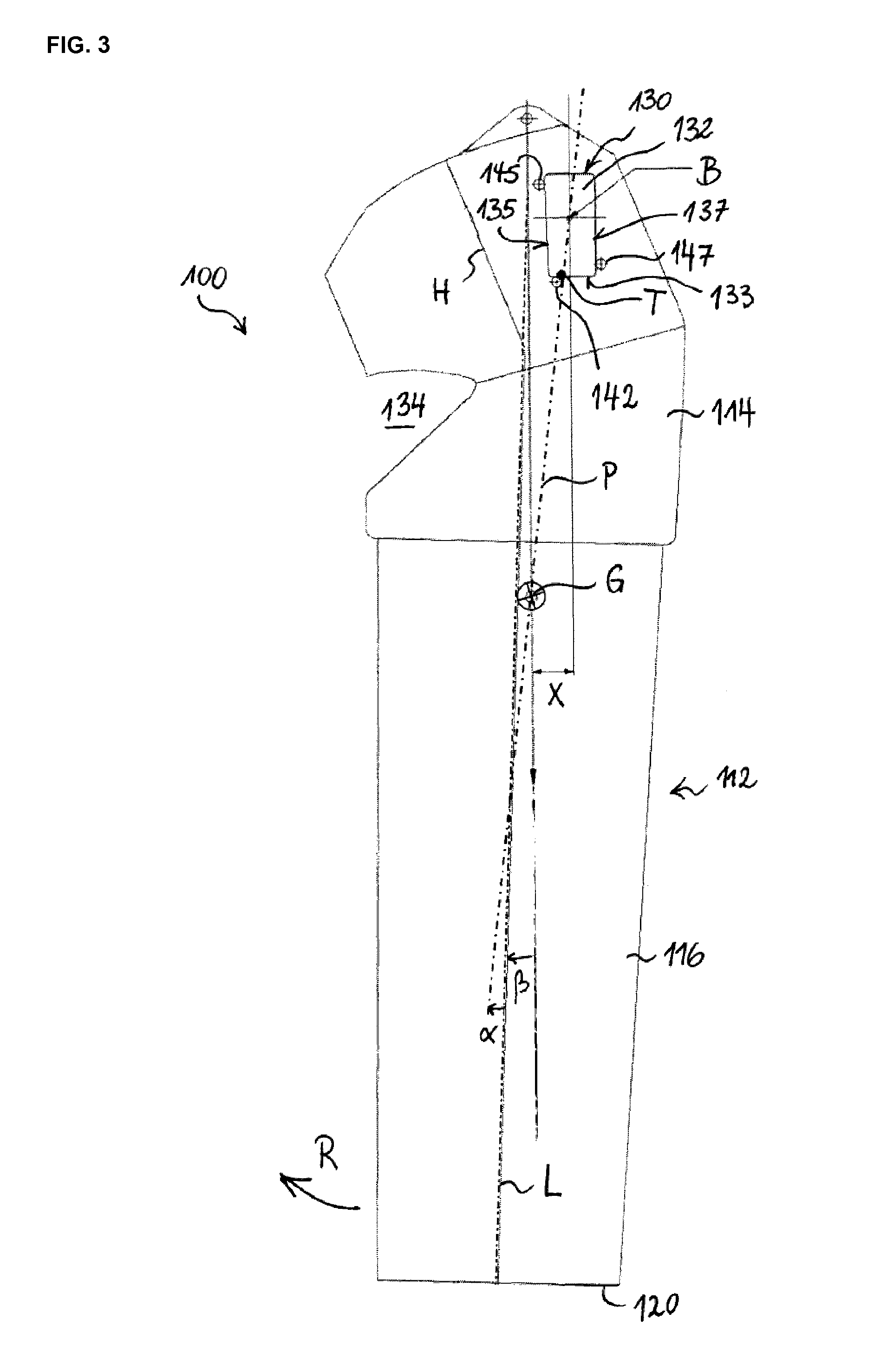
[0052]a chute 100 shown in FIG. 3 has a chute body 112 with an upstream mounting head 114. The chute body 112 has an elongated downstream chute portion 116 that extends along a longitudinal axis L. During operation, the chute portion116 provides a sliding surface, on which charge material slides to a downstream outlet 120 from which charge material (such as e.g. coke, ore, pellets, sinter etc.) leaves the chute body 112. The downstream chute portion 116 as such is of conical or cylindrical tubular construction, preferably with a fully closed outer shell in circumferential direction about axis L.

[0053]FIG. 3 shows the chute 100 in its actual replacement position. The chute 100 is designed so that in this position, the longitudinal axis L of the main chute portion 116 is at a small angle β to the vertical. The angle β has comparatively small angular measure in the raising sense R, i.e. in the range 0°≦β≦+5°, for example β=1.5−2.5°. The exchange position is not absolutely, but neverthe...

second embodiment

[0063]FIG. 4 shows the upstream region of a chute 200 concerning which only main differences with respect to the previous embodiment will be detailed. Identical or functionally identical features are provided with reference signs having an incremented hundreds digit in FIG. 4. As a noteworthy difference, the acute angle α of FIG. 4 is slightly negative, i.e. satisfies, 0°>α≧−5° (the positive sense of angles being the raising sense R). Accordingly, a torque reversal does occur, but due to the small absolute value of α reversal does not occur during normal operation. The chute is designed so that reversal occurs only when the chute 200 is pivoted to its exchange position, just before reaching the position illustrated in FIG. 4. Accordingly, a self unblocking function is achieved with this design, whereas the chute 100 can still be easily exchanged, because the suspension is also designed as “free suspension” i.e. permits tilting in the raising sense R (unless a safety pin is engaged)....

third embodiment

[0065]FIG. 5 illustrates a distribution chute 300. Again only main differences will be described because the chute 300 is very similar in design to the chute of FIG. 3 especially as concerns the position of the suspensions 330 placed closer to the bottom of the chute body 316, namely by distance X compared to a typical central suspension coinciding with the pivoting axis.

[0066]The chute 300 has a suspension 330 formed of a single coherent protrusion 322 that is of trapezoidal shape tapering towards the outlet of the chute 300 and symmetrical about its longitudinal axis. This shape provides a self-positioning function during the final stage of mounting the chute 300 to the support flanges. In consequence, as another benefit, the corresponding support flanges (not shown) have two lower protrusions 343, 345 that carry the weight of the chute by engaging the lateral surfaces 335, 337 at the tip of the trapezoidal protrusion 332. A torque resisting function is also assumed by one of thes...


PUM

PropertyMeasurementUnit
angleaaaaaaaaaa
bend angleaaaaaaaaaa
angleaaaaaaaaaa

Abstract

A distribution chute for a charging device, a charging device having the same, and a methods for mounting and dismounting such chute, the chute including an upstream mounting head and a chute body, at least two lateral suspensions on the mounting head for mounting the chute to two corresponding support flanges pivotable about a pivoting axis for raising an outlet to a charging position and for lowering the outlet to a charging position, where the suspensions define a first and a second tilt point about which a weight of the chute exerts torque onto the support flanges of the charging device when the chute is mounted to the charging device, where the ratio of the distance between each of the tilt points and the pivoting axis to the distance between the first and second tilt points amounts to 0.25 at most, the suspensions being arranged so that an oriented acute angle from the longitudinal axis to a plane through the tilt points and the center of gravity has an angular measure in the range from −5° to 15°.

Description

TECHNICAL FIELD[0001]The present invention generally relates to a charging device of the type that rotates and pivots a distribution chute about a rotational axis and a pivoting axis respectively. Specifically, the invention relates to a charging device for burden distribution in a blast furnace for producing pig iron or in any similar shaft furnace or metallurgical reactor.[0002]More specifically, the invention relates to the distribution chute itself and to an improved arrangement of the suspension device for mounting the chute to the charging device.BACKGROUND ART[0003]Known charging devices are designed to support, to rotate and to pivot the chute. Typically, rotation and pivoting is about two respective perpendicular axes so as to distribute bulk material in circumferential and radial directions, e.g. on a charging surface inside a blast furnace. In a widespread design, the chute used in this kind of charging device has a chute body, in which at least a downstream chute portion...

Claims


Application Information

Patent Timeline
Patent Type & Authority Patents(United States)
IPC IPC(8): B65G11/00B65G11/12C21B7/20F27B1/20F27D3/00F27D3/10
CPCB65G11/12C21B7/20F27B1/20F27D3/0033F27D3/10Y10T29/49815Y10T29/49826B65G69/0441
Inventor THILLEN, GUYTHINNES, CLAUDELONARDI, EMILEDEVILLET, SERGE
Owner PAUL WURTH SA
Why Eureka
Try Eureka