Device and method for localized force sensing

a localized force and sensing technology, applied in the field of electronic devices, can solve the problems of limiting the flexibility and usability of presently known force enabled input devices, presently known force/touch input devices are limited in their ability to accurately determine, etc., to facilitate localized bending zones uniformly, facilitate the use of improved device usability, and improve user interface functionality

Active Publication Date: 2015-07-07
SYNAPTICS INC
View PDF25 Cites 21 Cited by
  • Summary
  • Abstract
  • Description
  • Claims
  • Application Information

AI Technical Summary

Benefits of technology

[0006]Embodiments of the present invention provide a device and method that facilitates improved device usability. The device and method provide improved user interface functionality through the use of a pliable component having a bending stiffness, overlaid upon a compressible layer having a compression stiffness to thereby facilitate localized bending zones uniformly distributed across a sensing surface of a capacitive input device. The ratio of the bending stiffness to the compression stiffness is configured such, in response to force applied to the input surface by an input object, the resulting compressed region is spread out over a plurality of force receiver electrode coordinate locations. Consequently, the force data associated with the coordinate locations may be interpolated to accurately determine the coordinate position and / or magnitude of the applied force.

Problems solved by technology

However, presently known force / touch input devices are limited in their ability to accurately determine the position and / or intensity at which force is applied.
This limits the flexibility and usability of presently known force enabled input devices.

Method used


Image

  • Device and method for localized force sensing
  • Device and method for localized force sensing
  • Device and method for localized force sensing

Examples


Embodiment Construction

[0024]The following detailed description is merely exemplary in nature and is not intended to limit the invention or the application and uses of the invention. Furthermore, there is no intention to be bound by any expressed or implied theory presented in the preceding technical field, background, brief summary or the following detailed description.

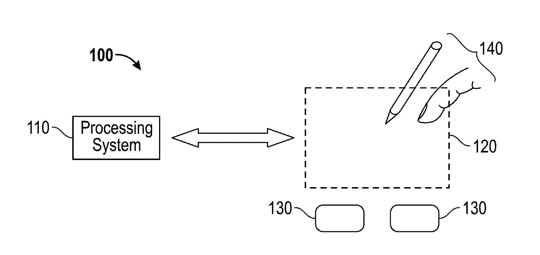
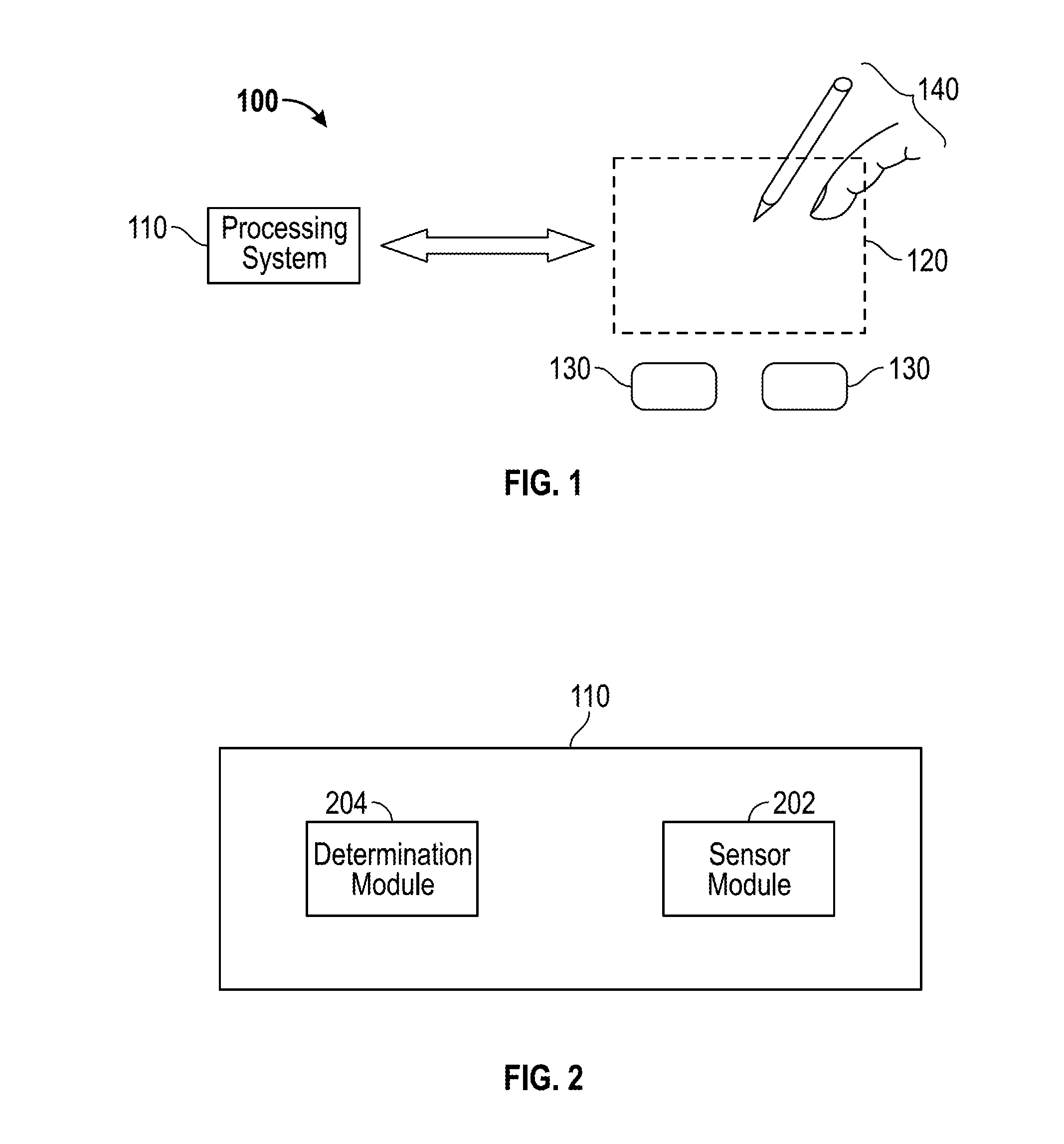
[0025]Turning now to the figures, FIG. 1 is a block diagram of an exemplary input device 100 in accordance with embodiments of the invention. The input device 100 may be configured to provide input to an electronic system (not shown). As used in this document, the term “electronic system” (or “electronic device”) broadly refers to any system capable of electronically processing information. Some non-limiting examples of electronic systems include personal computers of all sizes and shapes, such as desktop computers, laptop computers, netbook computers, tablets, web browsers, e-book readers, and personal digital assistants (PDAs). Additiona...


PUM

PropertyMeasurementUnit
compressibleaaaaaaaaaa
thicknessaaaaaaaaaa
Young's Modulusaaaaaaaaaa

Abstract

A device and method for operating a capacitive input device configured to sense input objects and their applied force in a sensing region, the device including a pliable component having an input surface and characterized by a bending stiffness, and first and second arrays of sensor electrodes. The input device further includes a third array of sensor electrodes and a spacing layer disposed between the third array. The pliable component is characterized by a compressive stiffness and configured to deform in response to a force applied to the input surface and to deflect the second array of sensor electrodes towards the third array of sensor electrodes, wherein the deformation of the input surface and the deflection of the second array of sensor electrodes is a function of the ratio of the bending stiffness of the pliable component and the compressive stiffness of the spacing layer.

Description

PRIORITY INFORMATION[0001]This application claims priority to U.S. Provisional Patent Application Ser. No. 61 / 770,074, filed Feb. 27, 2013.FIELD OF THE INVENTION[0002]This invention generally relates to electronic devices, and more specifically relates to sensor devices and using sensor devices for producing user interface inputs.BACKGROUND OF THE INVENTION[0003]Input devices including proximity sensor devices (also commonly called touchpads or touch sensor devices) are widely used in a variety of electronic systems. A proximity sensor device typically includes a sensing region, often demarked by a surface, in which the proximity sensor device determines the presence, location and / or motion of one or more input objects. Proximity sensor devices may be used to provide interfaces for the electronic system. For example, proximity sensor devices are often used as input devices for larger computing systems (such as opaque touchpads integrated in, or peripheral to, notebook or desktop com...

Claims


Application Information

Patent Timeline
Patent Type & Authority Patents(United States)
IPC IPC(8): G01L1/00G01L1/14G01R27/26G06F3/041
CPCG01R27/2605G01L1/146G06F3/0414G06F2203/04103G06F3/0446G06F3/0445G06F2203/04105G06F2203/04102G06F2203/04106G06F2203/04111G06F2203/04112
Inventor KALLASSI, PASCALE ELMACKEY, BOBHSIEH, LIN-HSIANG
Owner SYNAPTICS INC
Why Eureka
Try Eureka