Inductively shorted bicone fed tapered dipole antenna

a dipole antenna and bicone technology, applied in the field of bicone and dipole antennas, can solve the problems of not allowing the rotation of the second element 90 degrees, the frequency location and combining of the and the complexity of the type of impedance. to achieve the effect of prolonging the low frequency response of the shorted bicone antenna

Active Publication Date: 2015-07-07
UNITED STATES OF AMERICA
View PDF3 Cites 11 Cited by
  • Summary
  • Abstract
  • Description
  • Claims
  • Application Information

AI Technical Summary

Benefits of technology

[0044]Accordingly, it is an object of the present invention to extend the low frequency response of a shorted bicone antenna by using a combined bicone and dipole antenna.

Problems solved by technology

Also the configuration did not allow a second element to be rotated 90 degrees away into another dimension from a first element.
This type of impedance is more complex, such as with the location of the resonance frequencies, because the parts of the antenna in each dimension are not fully isolated from each other.
For dimensional resonances, their frequency locations and combining can become complex, since continuous antenna elements have no distinct boundaries between the dimensions in which different sized pieces of an element can independently resonate.
At higher frequencies, it is difficult to see any band overlapping since the antenna is more broadband and resonances are broadened significantly.

Method used


Image

  • Inductively shorted bicone fed tapered dipole antenna
  • Inductively shorted bicone fed tapered dipole antenna
  • Inductively shorted bicone fed tapered dipole antenna

Examples


Embodiment Construction

)

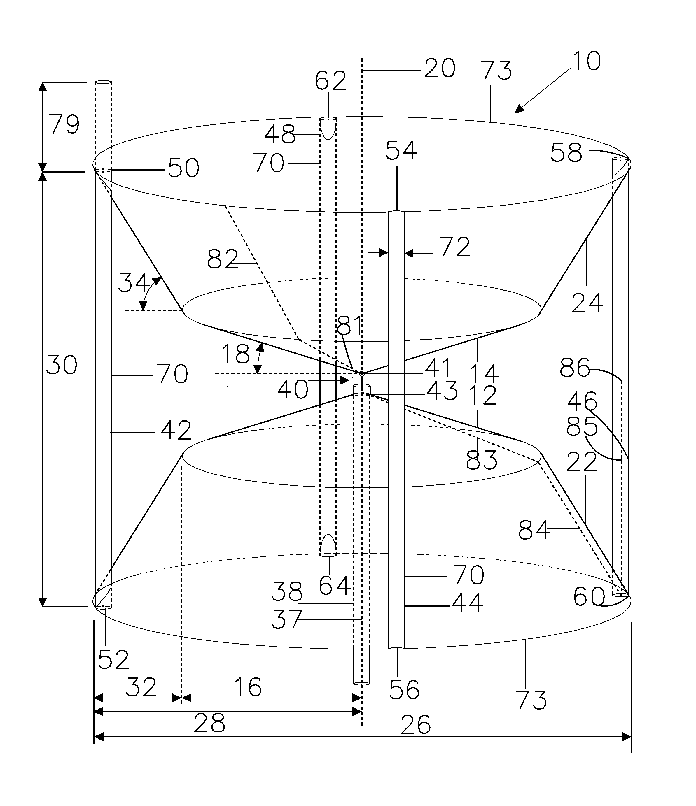
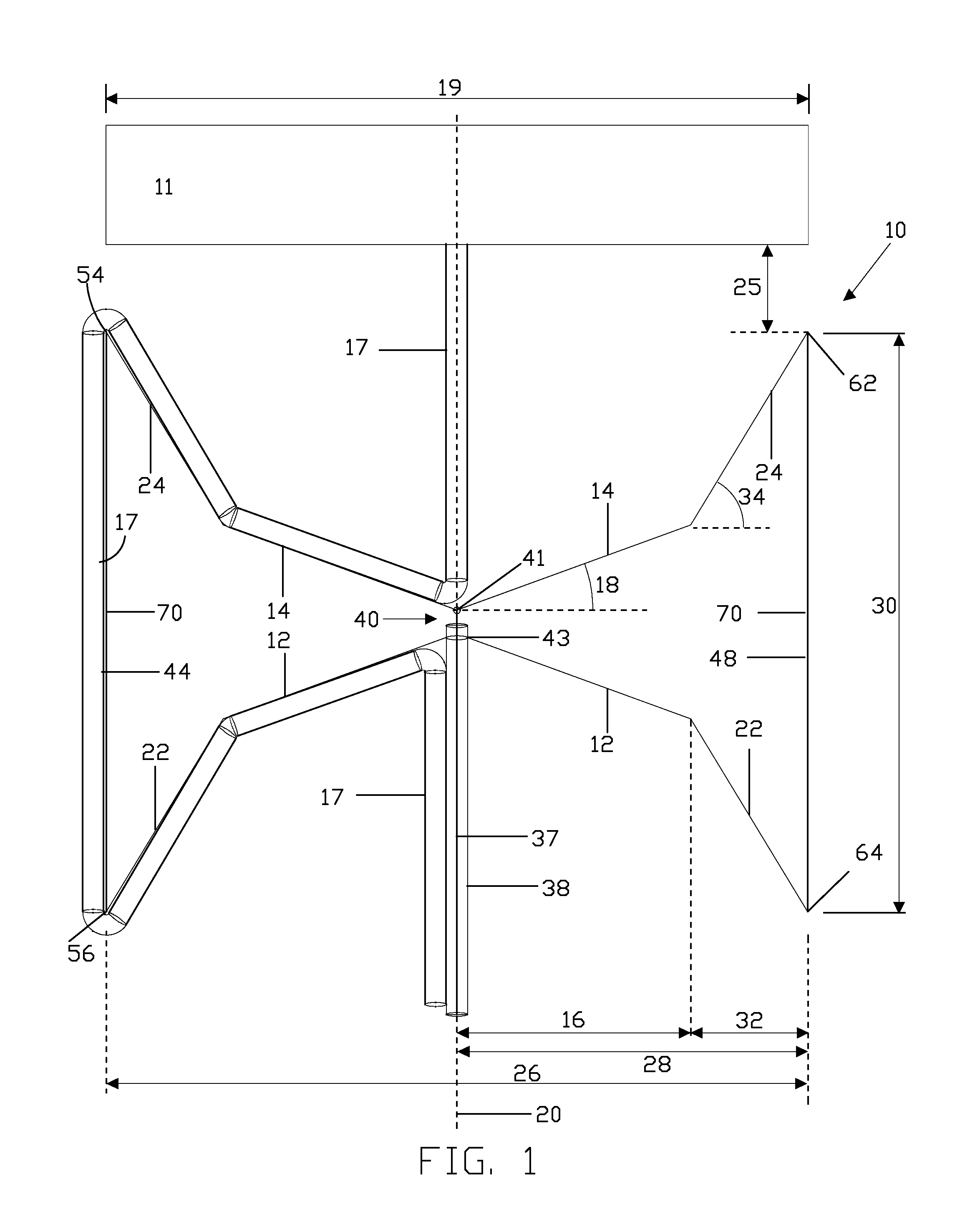
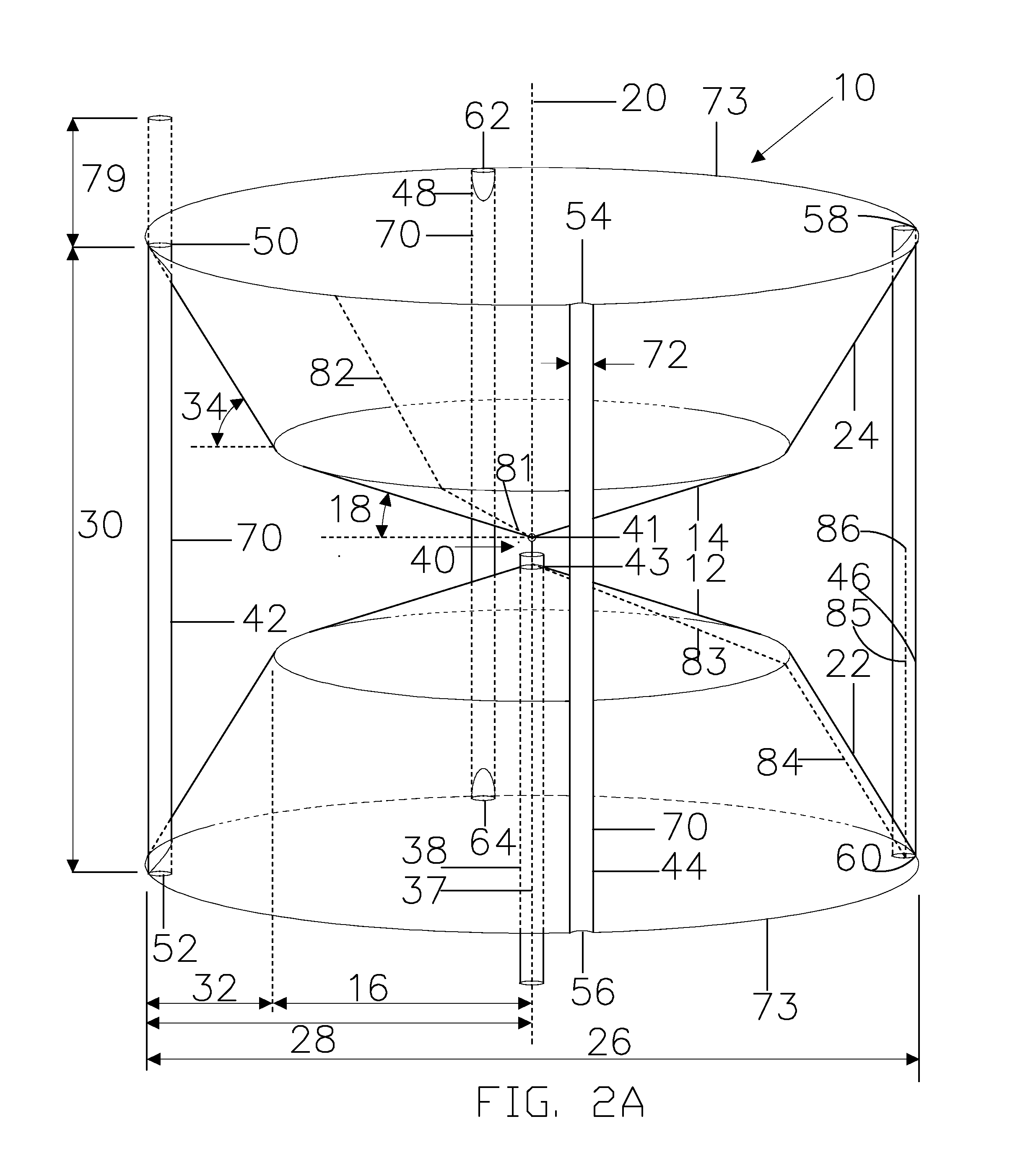
[0059]In order to improve the low frequency response of the antenna, the cut-in frequency of the shorted bicone should be lowered. A simple solution is to scale the antenna size according to the new cut-in frequency, which would increase its diameter and height. However, the diameter cannot be increased since it is fixed at the maximum inner diameter of the antenna's radome, which is defined as a physical structure which covers and protects the antenna. The radome can take on any shape and for the preferred embodiment it has a cylindrical shape with a curved inner surface and a hemispherical cap.

[0060]Even with a fixed diameter, the height could not be increased since an increase in height would increase the feed angle which would cause the antenna characteristic impedance Z0 to increase causing a mismatch. A solution is to convert the bicone part of the antenna into a bicone fed dipole of larger height with factors as noted below. The increased height of the overall larger antenna...


PUM


Abstract

An antenna for passing a cable to a second antenna includes shorts positioned along a circumferential perimeter of the antenna, first and second bicone sections of oppositely directed conductive cone sections energized at respective apices and opening along an antenna axis, first and second dipole sections, where the first dipole section is joined together with and extending from the first conical section to the circumferential perimeter of the antenna, and where the second dipole section is joined together with and extending from the second conical section to the circumferential perimeter of the antenna.

Description

STATEMENT OF GOVERNMENT INTEREST[0001]The invention described herein may be manufactured and used by or for the Government of the United States of America for governmental purposes without the payment of any royalties thereon or therefor.CROSS REFERENCE TO OTHER PATENT APPLICATIONS[0002]None.BACKGROUND OF THE INVENTION[0003](1) Field of the Invention[0004]The invention generally relates to RF antennas and more specifically to bicone and dipole antennas.[0005](2) Description of the Prior ArtResonant Antennas[0006]Antennas that have two or more relatively isolated paths from their feed points to their ends, on two or more dimensions of a structure, or have two or more relatively isolated or independent elements, can have a resonance associated with each path or element. For example, the elements of one of the bifilar helixes of the quadrifilar helix described in U.S. Pat. No. 5,138,331 (herein incorporated by reference in its entirety for background information only), are an example o...

Claims


Application Information

Patent Timeline
Patent Type & Authority Patents(United States)
IPC IPC(8): H01Q13/04H01Q13/06H01Q9/28
CPCH01Q13/04H01Q13/06H01Q9/28
Inventor JOSYPENKO, MICHAEL J.
Owner UNITED STATES OF AMERICA
Why Eureka
Try Eureka