Stabilizer brake for firearm

a technology of stabilizer and firearm, which is applied in the direction of weapon components, muzzle attachments, weapons, etc., can solve the problems of slow departure of combustion gases, increased noise, and increased noise, so as to reduce flash, reduce recoil, and reduce muzzle rise

Inactive Publication Date: 2015-07-14
INNOVATOR ENTERPRISES
View PDF7 Cites 24 Cited by
  • Summary
  • Abstract
  • Description
  • Claims
  • Application Information

AI Technical Summary

Benefits of technology

[0008]Testing has found that the Applicant's multi-chambered sleeved muzzle brake to substantially reduce recoil, reduce muzzle rise, reduce flash, and redirect noise (away from the shooter towards the target) while having no adverse effect on bullet velocity.

Problems solved by technology

In addition, muzzle brakes, besides redirecting gases, may slow the departure of combustion gases.
However, a disadvantage of muzzle brakes is that they often substantially increase the total noise level.
Most firearms are loud to begin with and any increase in noise can be painful or potentially harmful to the shooter's hearing.

Method used


Image

  • Stabilizer brake for firearm
  • Stabilizer brake for firearm
  • Stabilizer brake for firearm

Examples


Embodiment Construction

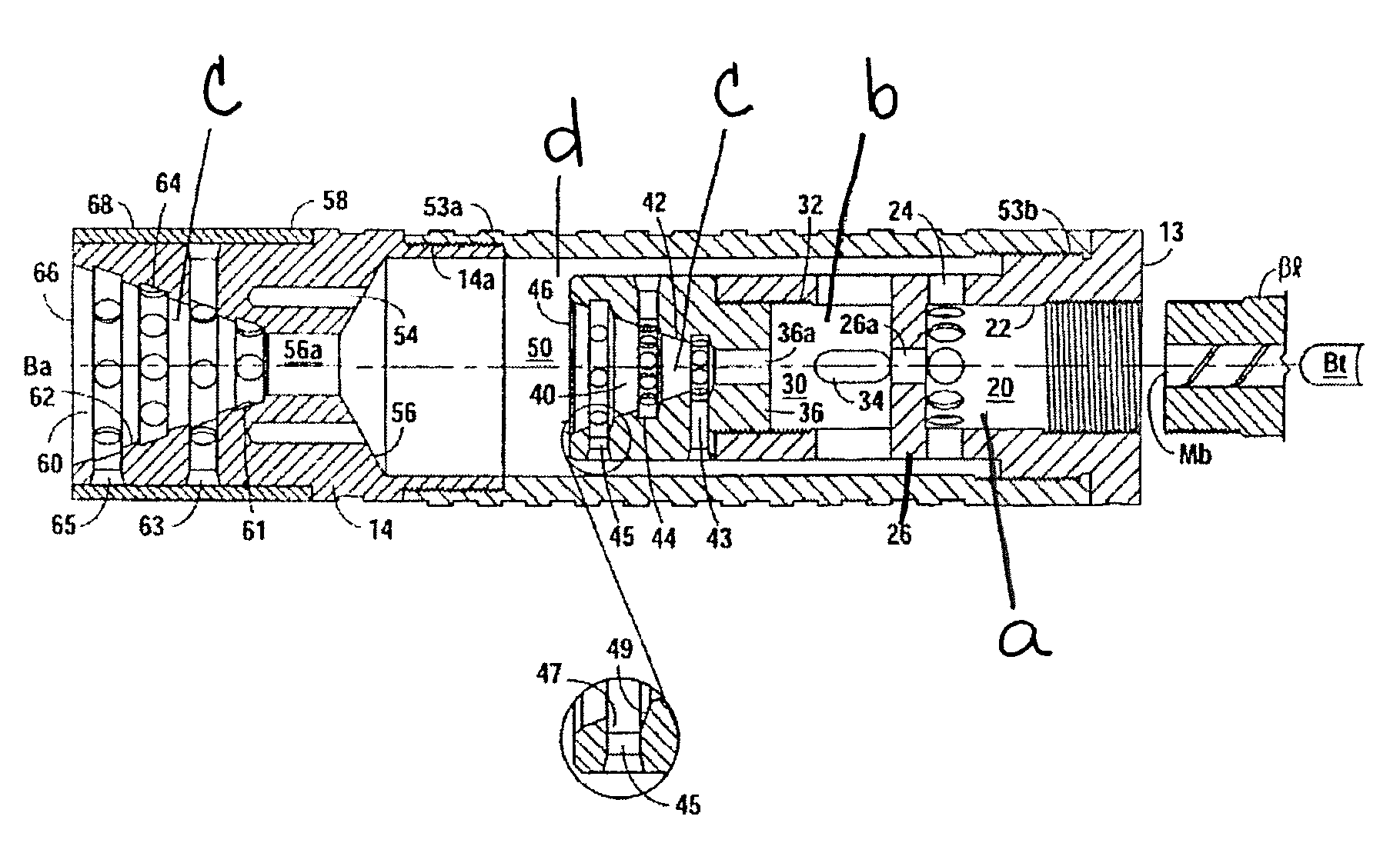
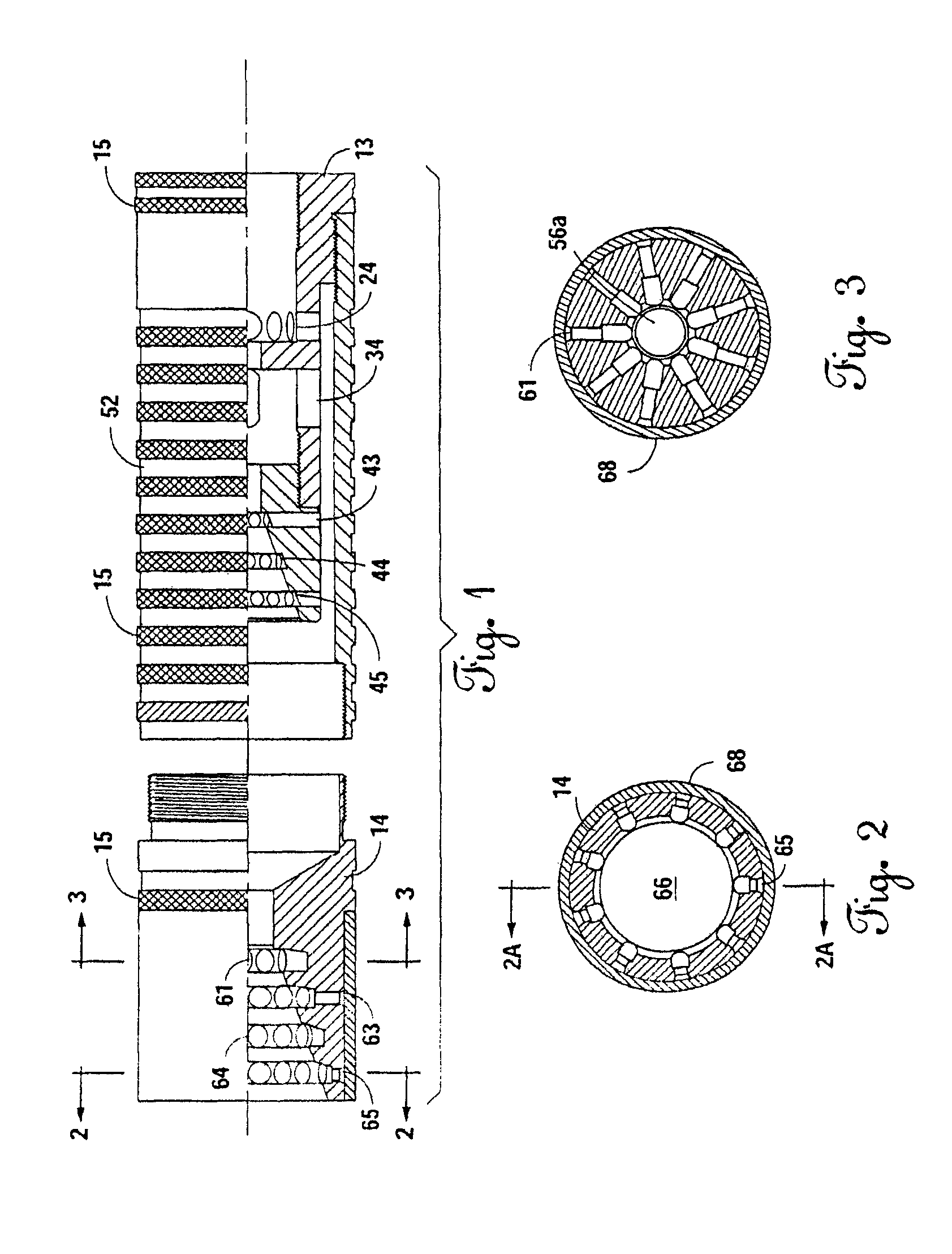
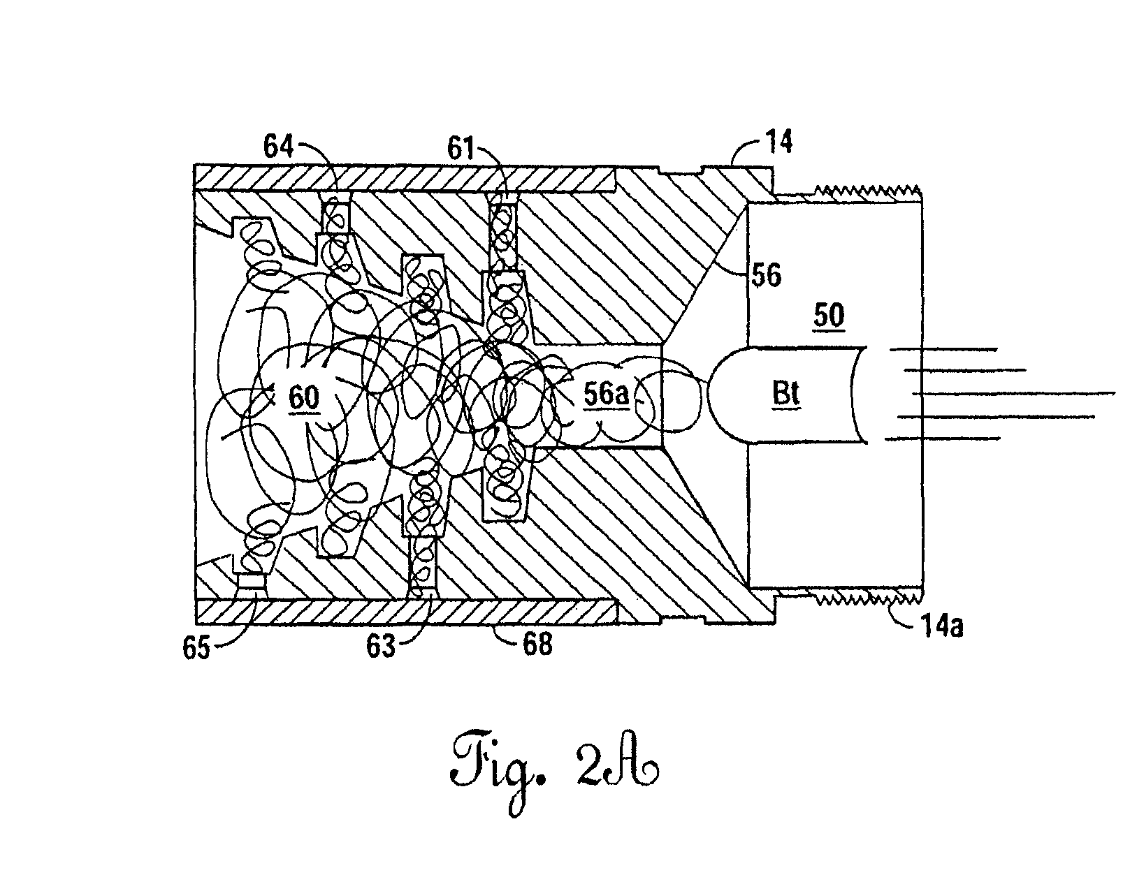
[0017]FIGS. 1-6 illustrate Applicant's muzzle brake 10, which may be comprised in one embodiment of one or more machinee, threadably engageable members. Illustrated here is Applicant's muzzle brake 10 comprising an inner member 13 having an outer surface 13a, a threaded portion 13b, and an end cap 13c. Threaded muzzle engaging portion 13d is also provided on inner member 13. A sleeve 52 is provided having a threaded near end 53a and a threaded far end 53b. An end member 14 is provided having a threaded portion 14a.

[0018]As seen in the Figures, for example, FIGS. 5 and 6, inner member 13 lies substantially within the sleeve and is threadably engaged thereto. Inner member 13 comprises multiple chambers 20 / 30 / 40 separated by end walls 26a / 36a through which a bullet Bt may pass through axial openings 26a / 36a, with close tolerances. The bullet Bt passes through the muzzle brake 10 along the bore axis Ba thereof. Moreover, the outer walls of inner member 13 are seen to, in part, define a...


PUM


Abstract

A muzzle brake and stabilizing device is provided for a firearm having a barrel, the barrel having a barrel axis, a muzzle, and a breech end. The muzzle brake comprises walls defining a first chamber adjacent the muzzle end of the barrel, the first chamber having a substantially closed end wall and side wall through openings. Walls defining a second chamber are proximate the first chamber, the second chamber has a substantially closed end wall and side wall through openings. Walls defining a third chamber are proximate the second chamber, the third chamber with a substantially open end and having side wall through openings. Walls defining an intermediate chamber are adapted to receive gases passing through the side walls of the first, second, and third chambers, the intermediate chamber with closed side walls and a substantially closed end wall. Walls defining a fourth chamber are proximate the end wall of the intermediate chamber, the fourth chamber having a substantially open end, and side wall closed end openings.

Description

[0001]This patent application claims the benefit of and priority to U.S. Provisional Patent Application Ser. No. 61 / 570,583, filed Dec. 14, 2011; and U.S. Provisional Patent Application Ser. No. 61 / 601,132, filed Feb. 21, 2012.FIELD OF THE INVENTION[0002]Muzzle brakes or stabilizers; moreover, a multi-chambered muzzle brake having an intermediate chamber therein.BACKGROUND OF THE INVENTION[0003]Muzzle brakes function, in part, to redirect and control a burst of combustion gases that follow a projectile. In a conventional muzzle brake, these gases are directed at an upward angle to the muzzle, thereby creating a force counteracting the upward rise of the muzzle. In addition, muzzle brakes, besides redirecting gases, may slow the departure of combustion gases.[0004]Typical muzzle brakes are ported expansion chambers, which have many openings that will allow communication between the muzzle and the outside environment.[0005]However, a disadvantage of muzzle brakes is that they often su...

Claims


Application Information

Patent Timeline
Patent Type & Authority Patents(United States)
IPC IPC(8): F41A21/00F41A21/30F41A21/34F41A21/36
CPCF41A21/36F41A21/30F41A21/34
Inventor CELLINI, VITO
Owner INNOVATOR ENTERPRISES
Why Eureka
Try Eureka