Mechanism for driving an indicator

a technology of indicator and mechanism, which is applied in the field of mechanical timepieces, can solve the problems of mechanism risking no longer working correctly, system or clockwork movement blockage,

Active Publication Date: 2015-07-14
GFPI SA
View PDF10 Cites 1 Cited by
  • Summary
  • Abstract
  • Description
  • Claims
  • Application Information

AI Technical Summary

Benefits of technology

[0024]Thus, each retractable tooth moves radially relative to the drive wheel. One advantage of this construction is that the shape of the retractable teeth remains symmetrical when the retractable teeth move such that they can work with other wheels of the movement including different pitch diameters from those of the wheels used in the mechanism according to the invention.

Problems solved by technology

However, the retractable tooth is a sliding element that is not kept in a given position and that could therefore inopportunely position itself in the active position in case of impact.
This would risk causing blockages of the system or breaking the clockwork movement.
The use of such an elastic element as a return spring is not optimal.
Additionally, in case of rupture or deformation of the elastic element, the mechanism risks no longer working correctly.
As a result, the retractable tooth will not be able to engage with a wheel having a different pitch diameter, much less in a bidirectional manner, in light of that asymmetry.
Such a mechanism using the action of a spring is not optimal.
This construction creates friction, which may be quite significant, thereby generating a significant loss of torque.
The risk is that after a certain amount of time, the retractable tooth will retract incorrectly or be kept in position incorrectly, which could cause poor operation of the system over the long-term.
The mechanism then risks no longer working correctly.

Method used


Image

  • Mechanism for driving an indicator
  • Mechanism for driving an indicator
  • Mechanism for driving an indicator

Examples


Embodiment Construction

[0049]In the present description, a period during which the information evolves by stepping may be a noncyclical period, such as the months of a Chinese calendar, or a period forming a cycle, such as the months of the Gregorian calendar, said information given by the indicator for example being able to be the day of the month.

[0050]In the example embodiment described below, the information provided by the indicator is the date for the day of the month, the cycle being four years, and the periods of the cycle being the different months of the year. We therefore have n=31 and m=3, the maximum value of the date being 28, 29, 30 or 31 depending on the months and years.

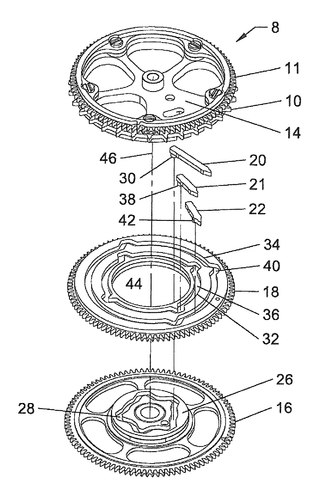
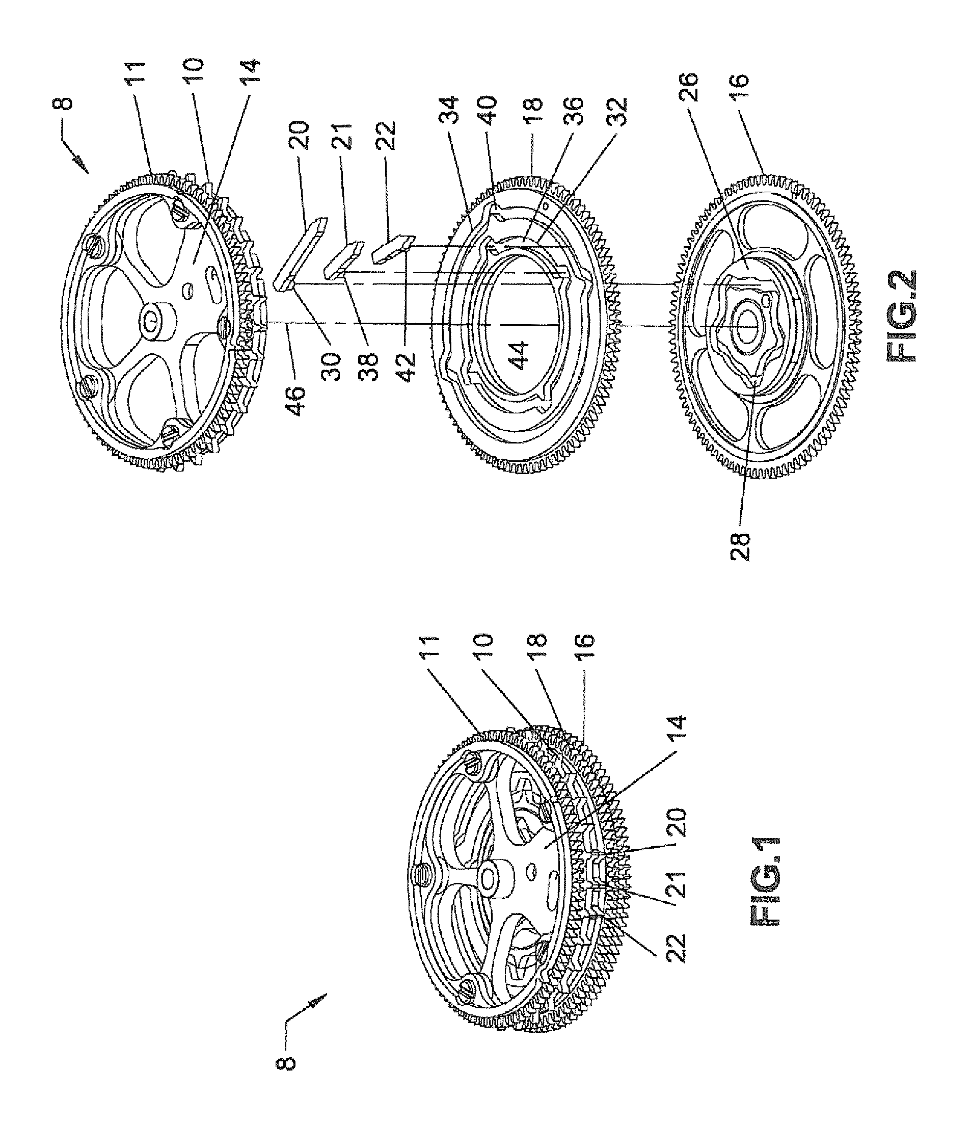
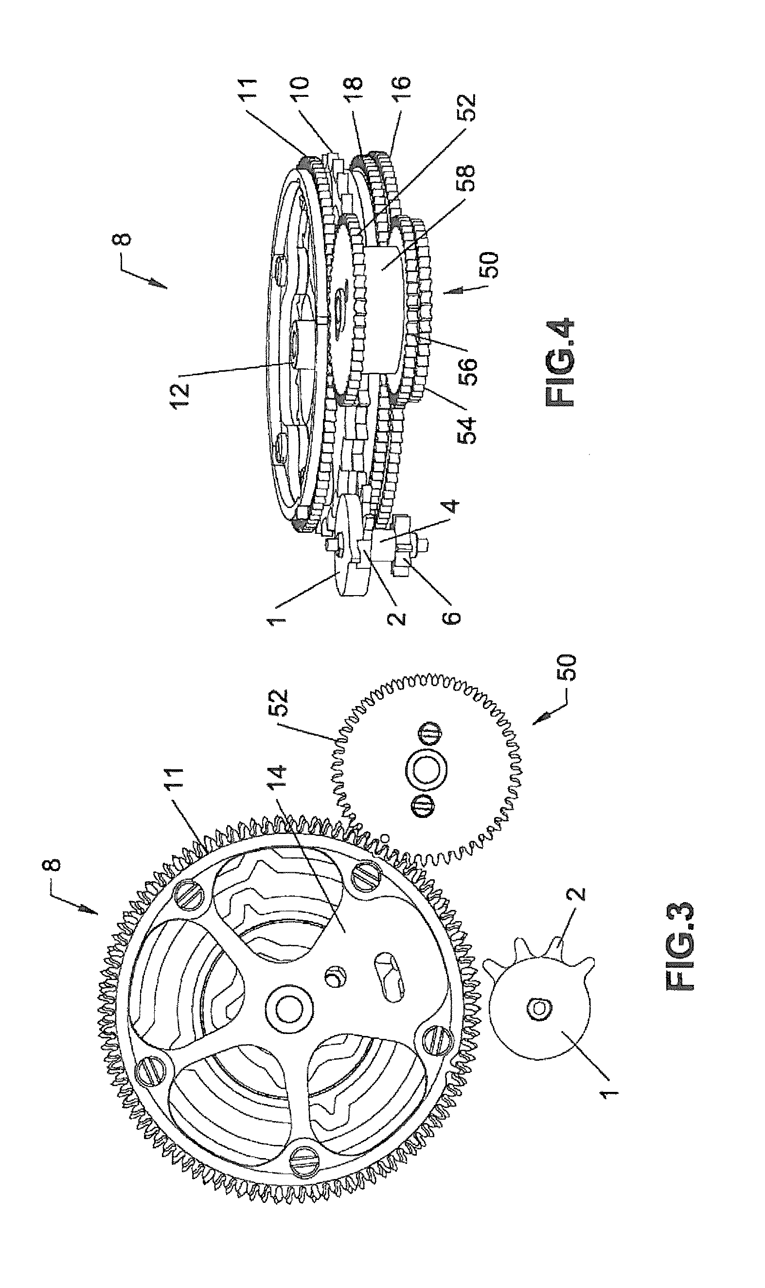
[0051]In this example embodiment, the drive mechanism according to the invention is a mechanism for driving a perpetual calendar indicator for a Gregorian calendar, the drive wheel being a dates wheel with 31 teeth arranged to advance by one step per day, that advancement being called a regular advancement.

[0052]In the pre...


PUM


Abstract

Mechanism for driving an information indicator connected to a timepiece movement and varies according to a plurality of periods, during each of which the information changes, step by step, to a maximum value that varies between n and n−m. The mechanism includes a drive wheel including a first set of gear teeth arranged to advance by n steps per period, m retractable teeth borne by the wheel, encoding cams corresponding to the retractable teeth, each cam corresponding to one maximum value n−x of the information, x being between 1 and m, for a period, and a drive unit to provide adequate rotation speed to the cams relative to the wheel such that, when the information reaches a maximum value n−x for a period, x retractable teeth pass in an operative position and then return to an inoperative position, the wheel advancing by x additional steps for the period.

Description

TECHNICAL FIELD[0001]The present invention relates to mechanical timepieces. It more particularly relates to a mechanism for driving an indicator of a piece of information connected to a clockwork movement and varying over several periods, during each of which that information evolves by stepping, up to a maximum value varying between n and n−m, said mechanism comprising:[0002]a first set of first drive pinions supplied with energy by the movement,[0003]a drive wheel comprising a first toothing arranged to mesh with the first set of first drive pinions to advance by n steps per period,[0004]a second set of second drive pinions supplied with energy by the movement, the first and second sets of drive pinions being positioned relative to one another such that they do not cooperate at the same time with the drive wheel, and[0005]m retractable teeth carried by the drive wheel, each being arranged to move between two positions, namely an active position for meshing with one of the second ...

Claims


Application Information

Patent Timeline
Patent Type & Authority Patents(United States)
IPC IPC(8): G04B19/253G04B19/24G04B19/243G04B19/02
CPCG04B19/2534G04B19/02G04B19/24G04B19/2432G04B19/2536
Inventor FORSEY, STEPHENNEBOISA, CHRISTOPH
Owner GFPI SA
Why Eureka
Try Eureka