
Audio systems and methods employing an array of transducers optimized for particular sound frequencies

a transducer and array technology, applied in the direction of electrical transducers, frequency response correction, semiconductor electrostatic transducers, etc., can solve the problems of inefficient components, inconvenient production of components, and inability to accurately generate sound over such a broad range of frequencies, so as to achieve accurate and efficient sound generation, improve sound quality, and improve sound quality

Active Publication Date: 2015-07-14
SHINDIG
View PDF77 Cites 14 Cited by
  • Summary
  • Abstract
  • Description
  • Claims
  • Application Information

AI Technical Summary

Benefits of technology

This patent provides systems and methods for generating audio with high efficiency and reduced distortion. It uses an array of audio transducers that can be optimized for specific sound frequencies to produce sounds with greater accuracy and volume. By analyzing the frequency composition of the audio stream, the system can adjust the resonant frequencies of the transducers to provide better audio quality in specific frequency bands. This results in a higher output volume of sound from the array with a given amount of input power. Overall, this technology improves the quality and effectiveness of audio production.

Problems solved by technology

Traditional audio systems provide flawed audio through inefficient techniques.
However, due to the physical limitations of these components, it is incredibly difficult and expensive to produce components that accurately generate sound over such a broad range of frequencies.
Moreover, such components typically operate in an inefficient manner that requires relatively large amounts of power.
These same limiting principles can also affect the performance of traditional microphones.

Method used


Image

  • Audio systems and methods employing an array of transducers optimized for particular sound frequencies
  • Audio systems and methods employing an array of transducers optimized for particular sound frequencies
  • Audio systems and methods employing an array of transducers optimized for particular sound frequencies

Examples


Embodiment Construction

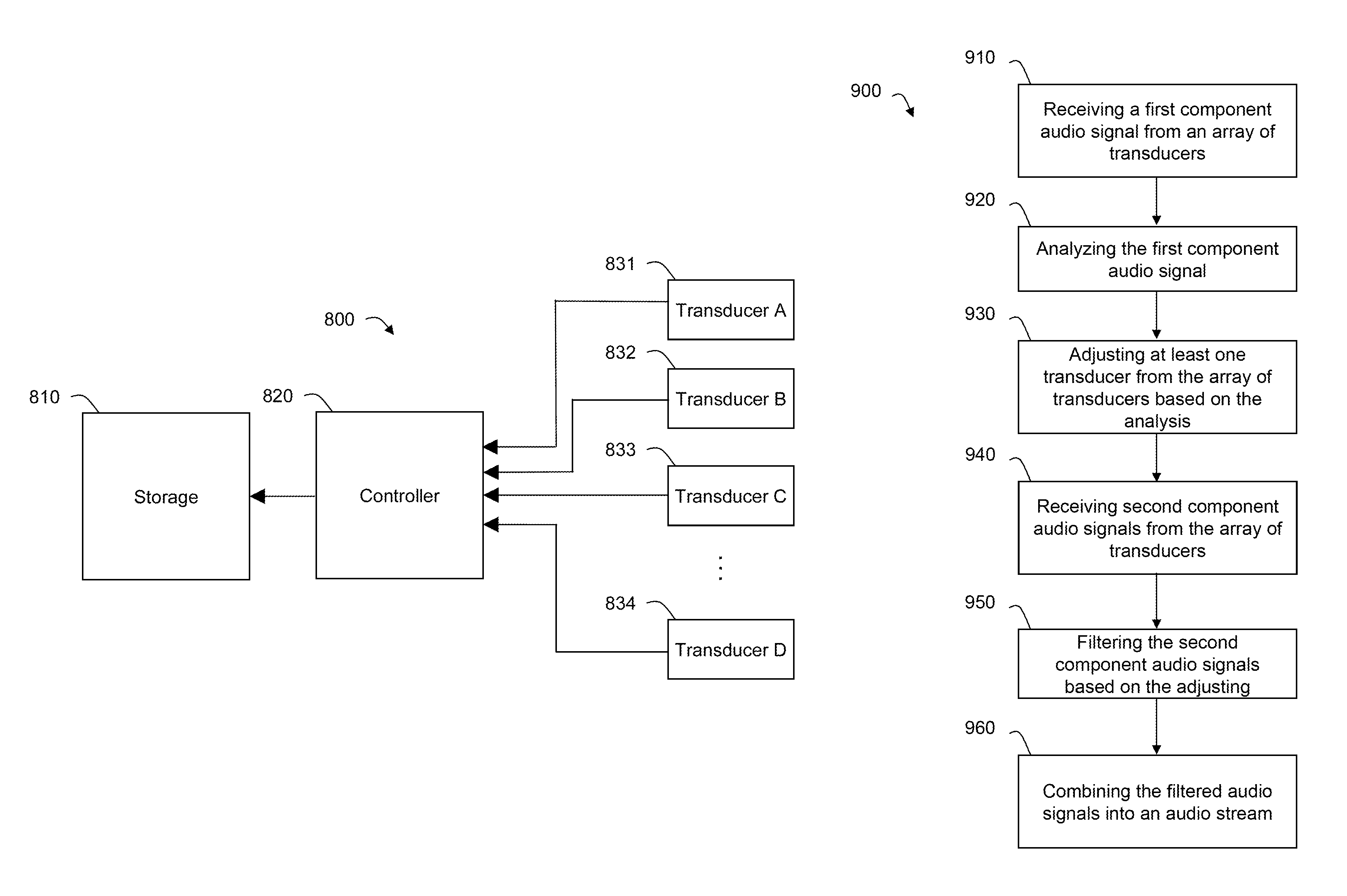
[0018]In accordance with the disclosure, an array of audio transducers can be provided and each audio transducer in the array can be optimized for a narrow range of sound frequencies. For example, each transducer in the array can have one or more physical characteristics that renders it ideal for producing (and / or detecting) sound within a narrow range of frequency (e.g., an optimum frequency or a resonant frequency). When operating at or close to its optimum frequency, the transducer can generate (and / or detect) sound with a higher efficiency and less distortion as compared to other frequencies. In some embodiments, the transducer may efficiently generate (and / or detect) sound at or close to its optimum frequency because the transducer's mechanical structure will naturally encourage vibrations at that frequency. In some embodiments, the transducer may generate (and / or detect) sound at or close to its optimum frequency with minimal distortion because the acoustic volume behind the t...


PUM


Abstract

Systems and methods for generating sound, detecting sound, and generating and detecting sound are provided. An array of audio transducers can be provided whereby each audio transducer in the array can be optimized for a narrow range of sound frequencies. When operating at or close to its resonant frequency, a transducer can generate (and / or detect) sound with a higher efficiency and less distortion as compared to other frequencies. Accordingly, sound may be divided into component signals such that each transducer is only responsible for generating (and / or detection) sound close to its resonant frequency. This sound reproduction (and / or detection) technique can increase efficiency, and therefore, can increase the total output volume that an array can generate using a given amount of input power when generating sound (and / or increase the total output power that an array can generate using a given amount of input volume when detecting sound).

Description

CROSS-REFERENCE TO RELATED APPLICATION[0001]This application claims the benefit of U.S. Provisional Application No. 61 / 355,984, filed Jun. 17, 2010, the disclosure of which is incorporated by reference herein in its entirety.FIELD OF THE DISCLOSURE[0002]This can relate to systems and methods for generating sound, systems and methods for detecting sound, and systems and methods for generating and detecting sound.BACKGROUND OF THE INVENTION[0003]Traditional audio systems provide flawed audio through inefficient techniques. For example, many traditional speakers contain only two or three components (e.g., a subwoofer, a mid-range and a tweeter), and each of the components is intended to cover a broad range of frequencies. However, due to the physical limitations of these components, it is incredibly difficult and expensive to produce components that accurately generate sound over such a broad range of frequencies. Moreover, such components typically operate in an inefficient manner tha...

Claims


Application Information

Patent Timeline
Patent Type & Authority Patents(United States)
IPC IPC(8): H04R3/00H04R1/02H04R3/04H04R3/06H04R1/40
CPCH04R3/04H04R1/406H04R3/005H04R3/06H04R1/2888H04R2430/03H04R19/005H04R9/063H04R9/06H04R29/00H03G5/005H03G5/165
Inventor GOTTLIEB, STEVEN M.
Owner SHINDIG
Learn More